Programmable Logic Controller PLC
Automation is one of the most innovative achievements of the human being. In search of survival, man evolved, and was discovering the forms of energy available on the planet, which uses them to their benefit, thus meeting their needs. The energetic modalities allowed the mechanization of diverse activities, drastically reducing the work of the hand of the human being, demanding, nevertheless, management and control activities, often extremely monotonous and repetitive.
In this way, with the development of automation, the human being freed himself from the control of repetitive tasks, going on to manage and plan more complex activities, proportional to the cognitive capacity of the human brain.
Industrial automation is an area of research that has gradually expanded its performance in recent years. The use of devices and the application of solutions developed in industrial automation have great repercussion, especially in the industrial sector. The applications are not summarized to replace the human work in exhaustive, monotonous and dangerous tasks; that bring improvements in the quality of processes, optimization of spaces, reduction in production time and costs.
Control systems are present in practically all industrial, commercial and service activities, being the basis of the automation of industrial processes.
The industrial processes are formed by mechanical, electrical, electronic, hydraulic or pneumatic equipment that, through successive operations using raw material and energy, will result in a final product and waste.
Basic Concepts of Programmable Controllers
There are various equipment used in industrial automation, however, the Programmable Logic Controller (PLC) and one of the most important. The PLC emerged at the end of the decade 1960 and revolutionized the controls and industrial controls. At that time, automation was almost entirely executed by relays based on fixed logic, or hardwired logic, resulting in huge electromechanical relay cabinets interconnected by electrical circuits and extensive spinning.

Typical Relay Panel
The first generation of PLCs used discrete components and had a low scale of integration. Its use was only viable when it replaced panels containing more than 300 relays. This equipment was known by the acronym PLC (Programmable Logic Controller).
According to the Electric Electrical Manufacturers (NEMA), it is a "digital electronic device that uses a programmable memory for internal storage of instructions for specific implementations, such as logic, sequencing, timing, counting and arithmetic, to control various types of machines and processes through input and output modules".
With the emergence of integrated circuits, it was possible to facilitate and disseminate the use of PLC on a large scale, improving the processing power and decreasing the size of the equipment.
Recently the PLC had proprietary architecture, in which each manufacturer produced the own model and developed the programming and simulation software exclusively for their equipment, that is, there was no portability. With the adoption of the IEC 61131-3 standard, the programming language was standardized and the solution for software and applications has been reached.
Currently, PLCs have specific control functions and communication channels that allow interconnection between computers and network, forming an integrated system.
The advantages of using PLC in industrial applications are innumerable and every day new ones arise, which result in greater economy, exceeding the cost of the equipment. Evolution offers a large number of benefits, for example:
• Higher productivity.
• Optimization of space in the factories.
• Improvement in the quality of the final product.
• High MTBF (mean time between failures).
• Under MTTR (machine stop time).
• Greater security for operators.
• Lower energy consumption
• Waste reduction.
• Reuse of cabling.
• Greater reliability
• Easy maintenance.
• Faster system design.
• Greater flexibility, satisfying a greater number of applications.
• Interface with other PLCs through a communication network.
The evolution of programmable controllers can divided into five generations.
In the first generation, the programming was done in Assembly, demanding of the programmer complete knowledge of the hardware of the equipment, that is to say, of its components the electronics.
In the second generation, medium-level languages emerged, with programs to convert the program developed by the user into a machine language.
In the third generation, the PLCs presented programming inputs, allowing their connection to keyboards or portable programmers.
In the fourth generation, the PLCs presented input to serial communication, enabling its programming directly from a team. The programming software installed in the computer allowed, in addition to programming and transfer of the program to the PLC, to test the operation of the program.
Fifth generation PLCs present protocols patterns of communication, facilitating the interface with other equipment and also with supervision systems.
PLC Structure and Operation
The PLC is a microprocessed device, constituted by a system microprocessor or a microcontroller, a monitor program, a program memory, a data memory, one or more input interfaces, one or more output interfaces and auxiliary circuits.
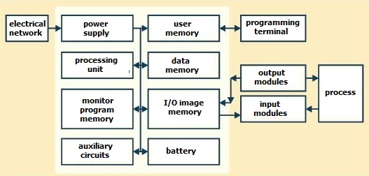
Power supply
The power supply of a PLC is intended to convert the supply voltage (110 to 220 VAC) to the supply voltage of the electronic circuits (5 Vcc for the microprocessor, memories and auxiliary circuits e12 VCC for communication with the programmer or computer ), as well as maintain charge the battery and provide voltage for the input and output power (12 or 24 VDC).
Processing unit
The CPU is responsible for the logical operation of all the circuits. In modular PLCs, the CPU is usually contained in a single card separated from the others. Already in PLC of smaller size, the CPU and the other circuits are generally contained in the same plate.
Battery
The battery used in PLC is intended to maintain the power of the real-time clock circuit and maintain the parameters or (when RAM memory is used), even in the absence of electrical power.
Monitor program memory
The monitor program is responsible for the general operation PLC, administering all PLC activities. This program can not be changed by the user, being stored in memories of the PROM, EPROM or EEPROM type, and works in a similar way to the operating system of the computers.
User memory
In this memory, the program developed by the user, which can be changed, making the programming flexible. This program is usually stored in RAM, EPROM, EEPROM and FLASH-EPROM memories, whose capacity varies according to the PLC model.
Data memory
Its purpose is to store the program data of the user, such as values of timers, counters, passwords, etc. In general, the data memory uses parts of the RAM memory of the PLC.
Input and output memory
This memory stores information about the states of the inputs and outputs of the PLC, functioning as a table where the CPU will look for information during the processing of the user program.
Auxiliary circuits
They are circuits responsible for the protection of faults in PLC operation, such as:
• Avoid the improper activation of the outputs when PLC power;
• Avoid the loss of information in the event of PLC deenergization;
• Avoid processing errors, identifying faults in the system microprocessor that emits error information.
PLC inputs and outputs
All PLCs have the same basic components. These components work together to bring information to the PLC from the field, evaluate that information and send information back to various fields. Without any of these major components, the PLC will not function properly.
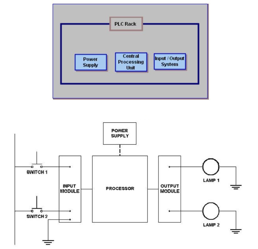
Digital (discrete) and analog variables are present in a process. Analog variable is understood to mean that it varies continuously as a function of time, such as, for example, the temperature of a room, which can assume any value within a certain range. Digital variables, on the other hand, assume binary situations, such as, for example, motor on or off, presence of a person or not.
For a PLC, through a program, to adequately control a certain process, it is necessary that it has input/output devices compatible with the process variables and with the desired control strategies.
The input and output (I/O) modules of a PLC connect the interface with the external system. There are several types of modules (analog, digital and intelligent), with a variable number of inputs and outputs. The PLC input modules receive signals from sensors and field buttons. The output modules communicate to the actuators what the control or signaling action will be.
In medium and large-sized PLCs, the I/O modules are fitted in slots located in the CPU box (Central Processing Unit) or in a separate expansion rack, allowing flexibility in the configuration of the PLC. The use of slots also allows the damaged module to be replaced quickly.
In small PLCs (microPLCs), the number of inputs and outputs is small and fixed (less than eight) and generally consists of digital signals.
The digital I/O modules operate with signals from two states: ON or OFF. The digital input modules are capable of detecting and convert input signals to logic voltage levels used in the PLC; the digital output ones convert the logic output signals used in the PLC into proper signals capable of energizing the actuators.
Some digital I/O modules work with continuous signals; others operate with alternating signals. For use in DC (direct current), the standard voltage value adopted is 24 V, as it allows a signal/noise ratio suitable for industrial environments. For AC modules (alternating current), the standard is 110 or 220 V.
Discrete Module (Relay)
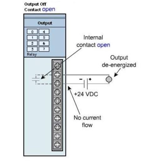
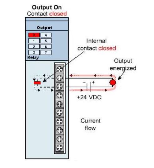
The term refers to an Off switching output. One type of PLC module that produces discrete signals is a relay module. It has a physical relay that opens or closes to make or interrupt a circuit connected to its terminals. The relay modules have several pairs; each of which is connected to the relay's internal contacts.
Open contact
Closed contact
Discrete Module (Transistor)
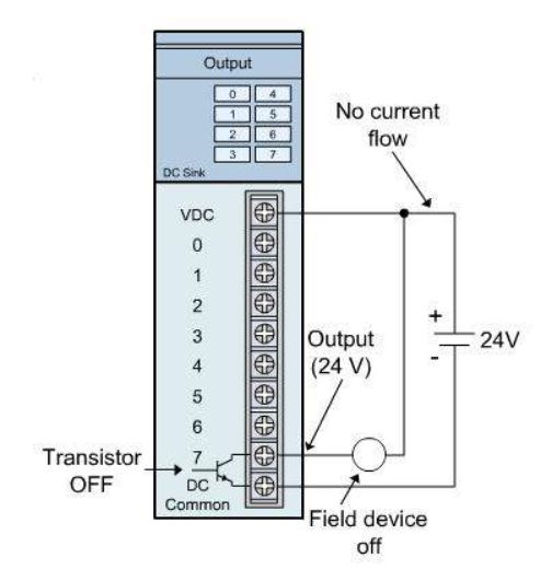
Another type of discrete module is the sinking output module, so named because conventional current flows to its terminal when a specific output is turned on. Conventional current flows from a positive to a negative potential.

Output not activated
Output activated
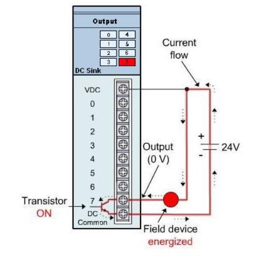
Representation of events when the output is activated:
1 - An NPN transistor is activated
2 - The output terminal goes to LOW
3 - Conventional current flows from the positive of the power supply through the field device to the sinking terminal of the output module through the transistor to the negative of the power supply.
AC input modules
AC input modules detect the presence or absence of AC voltage and convert that voltage to a low level for input to the CPU. The AC voltage indicates the status of the field device. The voltage level is usually 24, 110 or 220 VAC. The modules are available for up to 1,000 VAC. A schematic diagram of the AC input module is shown below. When the field device completes the input circuit, there is a path to AC. An LED on the front of the module indicates that the input is present.
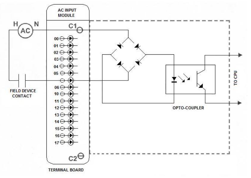
A rectifier converts AC to DC. The optical coupler isolates the CPU input module and effectively reduces the DC voltage level to a safe level for CPU operations.
Most AC input modules use an external AC power supply for "interrogating" field devices. Integrated AC power supplies increase the size of the module and require additional heat dissipation considerations.
AC inputs can use a common neutral connection for multiple points or there can be an "isolated" neutral for each point for additional protection against failures. The input module shown in the image above uses C1 neutral for points 00-07 and C2 neutral for points 10-17. Analog AC input modules are not commonly used because there are no standardized analog AC current or voltage signals.
DC digital input modules
Discrete DC input modules detect the presence or absence of DC voltage and convert this voltage to a low level for input to the CPU. The DC voltage is used to indicate the status of the field device. The image below shows a schematic diagram of the DC input module.

The DC voltage can be supplied by the input module (collector input) or it can be supplied by an external power supply (source input).
As with AC input modules, the input is coupled to the CPU for CPU isolation and protection. An LED provides an indication when the input is present (true).
DC analog input module
The analog DC input modules detect a DC voltage or current level, convert this variable into a proportional digital signal and transmit this data to the CPU for processing. The modules can be configured to operate in standard instrumentation signal ranges, such as 4-20 mA, 10-50 mA, 0-10V.
A schematic diagram of an analog DC input module is shown below:
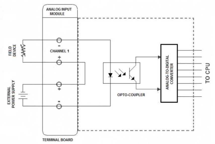
After the module converts the analog value to digital, the PLC can activate and deactivate the control functions in predefined analog values. For example, when the analog input value reaches 70%, an alarm sounds.
AC output modules
The AC output modules control the ON / OFF states of the AC output field devices, such as relays, coils and solenoids. They typically do not use power for field devices. The image below is a schematic diagram of the module.
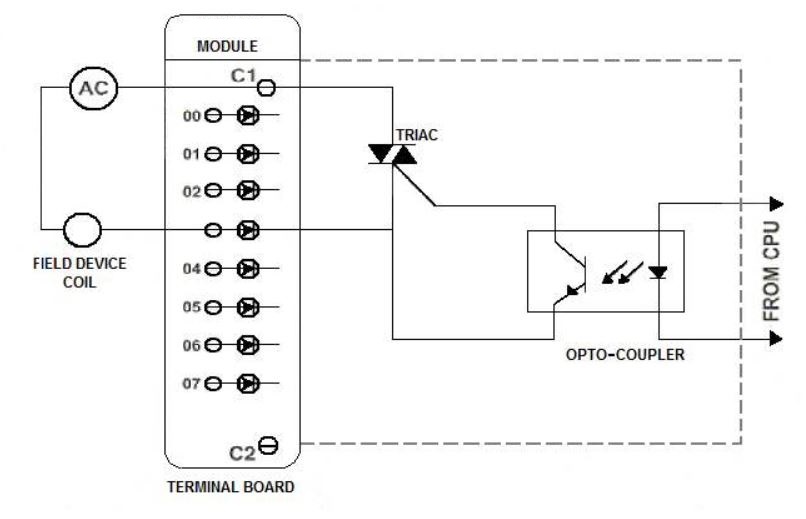
The CPU uses a low voltage DC signal to activate an optocoupler on the output module. The opto-coupler activates a TRIAC or SCR which, in turn, completes the current path to the external power supply and the field device. As with most PLC modules, the voltage rating and number of points are selectable and the outputs can have common or isolated neutrals.
DC discrete output modules
Discrete DC output modules control the on/off states of the DC output field devices. The power is supplied by an external power supply. A schematic diagram of the module is shown below:

The CPU sends a low-level DC signal to an optocoupler that completes the path of the external DC current that energizes the output field device. Field device connections can be "sinked" or "sourced".
DC analog output modules
Analog DC output modules convert digital data from the CPU into analog data for use in the field device. A digital to analog converter (D/A) on the module performs the conversion. Below for a schematic diagram of the module.
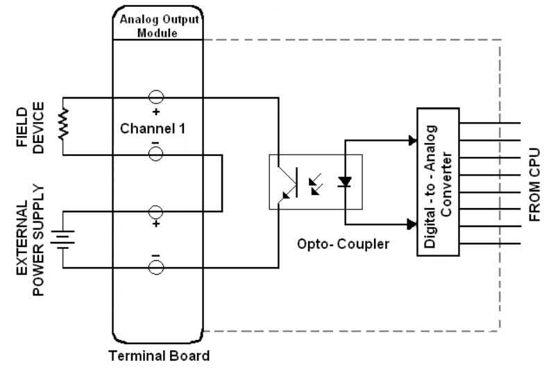
Analog outputs conform to standard instrumentation signals (4-20 mA, 10-50 mA, 0-5V, 0-10V). An external DC power supply is used to power the output field device and the optical coupler on the module.
Analog Inputs and Outputs Signals
Analog signals are widely used in PLC programs. A PLC can only work with values 0 and 1.
This is great for digital signals. They are 0 or 1 and therefore relatively easy to work with. But what about analog signals? Analog signals are continuous signals that can vary over time.
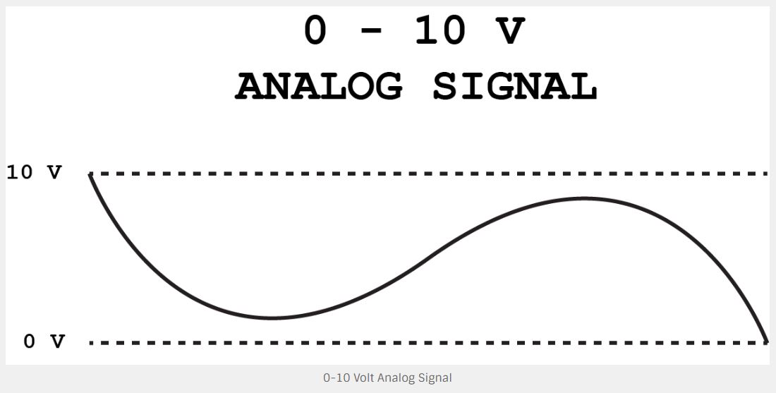
For example, you can have an analog signal from 0 to 10 volts. This signal can vary from 0 to 10 volts and have any voltage level in between. And since analog signals are continuous, this signal always represents a voltage level at any time. If you look at the diagram below, you will see that the analog signal can have any value between 0 and 10 volts.
The question now is: how does a PLC handle all these different values?
Let's say you have a 5-volt analog signal on the PLC. We cannot represent it with Boolean values, because they can only have the values 0 and 1.
The answer is binary numbers!
Representing analog signals with binary numbers
As mentioned earlier, a PLC can only work with the two values 0 and 1. But this prevents us from working with analog signals. Because what is really happening is that the PLC works with binary numbers. This is due to the fact that a PLC or a microcontroller are really just advanced electrical circuits made of transistors. As a transistor can only be activated or deactivated, these two states represent the values 0 and 1.
But that gives us only two states. Very useful for digital signals, but not for analog. To understand how analog inputs work on a PLC, you need to understand binary numbers.
Binary numbers is the numbering system used by a PLC or any other computer. The system has only two numbers, compared to the 10 base numbering system, where we have 10 numbers from 0 to 9. Binary is just another way of writing numbers.
Bits and bytes
A single digit binary number is called a bit. A bit can contain 0 or 1.
If you combine these bits and create multi-digit numbers, things start to get interesting.
In many PLCs, an analog signal is represented by a word (2 bytes). A binary word with zeros looks like this:
00000000 00000000
A 16-digit binary number can represent values from 0 to 65,535. This is only half the truth for PLCs. The first bit is used to signal the number, providing a positive or negative value.
Therefore, with 1 bit for the signal, we have 15 bits remaining to represent the analog value. The binary number can therefore represent values from -32,768 to 32,767.
A/D converter
When the analog input signal enters the PLC, it passes through an A/D converter or analog to digital converter.
This is the component on the PLC's analog input board that transforms the analog signal into digital signals. It is these digital signals that will eventually provide our representation of binary value on the PLC.
Before getting to know the A/D converter, it is important to understand what type of analog signal you are dealing with.
The three most common types of analog signals in PLC programming are:
• Voltage
• Current
• Resistance
The reason we need to know about the type of signal is because we need to know the range of the signal. A widely used type of analog signal is 4-20mA.
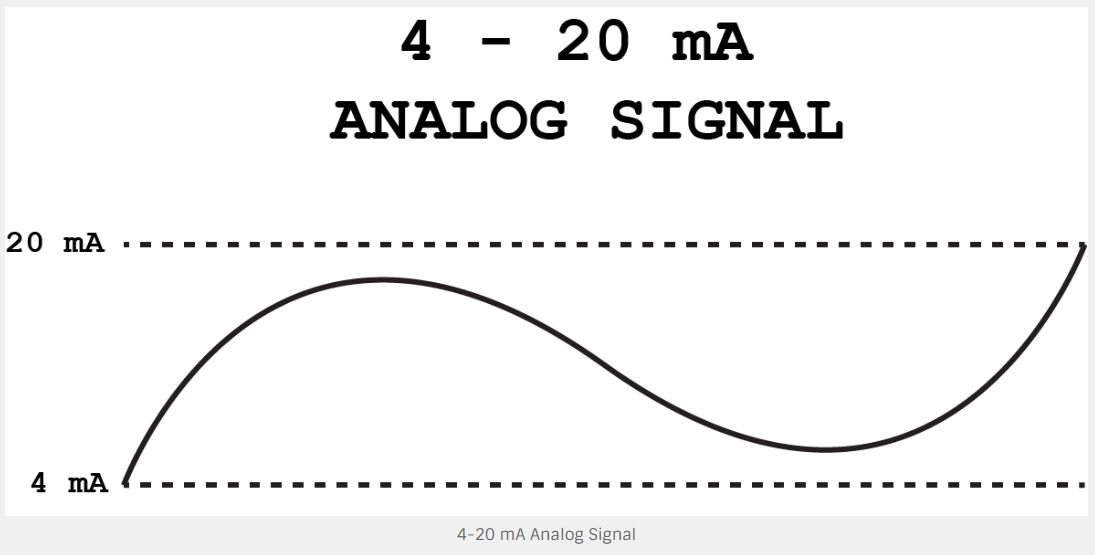
In the 4-20mA signal there is a range of 16mA (20mA - 4mA). An analog value is often placed in a 16-bit word on a PLC. This is because the A/D converter converts the analog signal to a 16-bit digital value.
You can buy analog input cards with different resolutions. This depends on how many bits the A/D converter needs to work. More bits gives us more numbers to represent the analog signal.
Resolution of analog signals
The number of bits you need to save in the analog value is called the resolution.
Think of it as your TV. It also has only a certain amount of pixels to represent an image. The same is true with analog to digital conversion. Just as we call resolution when talking about the number of pixels on television, we also call resolution when talking about analog values represented by a number.
Resolution is very important when dealing with analog signals in PLC programming. Upon entering the analog input card, the analog signal will be divided into a value between 0 and 32,767. Dividing the analog value by 32,767 gives us a certain resolution.
Every time our value increases by 1, it means that the analog signal has increased by x mA.
Analog Signal Range
Analog signals tend to be very sensitive. Although it is our intention that a signal range is 4-20mA, the signal can sometimes exceed these limits. When that happens, we want to be able to see it on the PLC. While not always the case, these overflows can mean that something is wrong. In order to detect them in the PLC program, we need what is called overflow and underflow of the range.
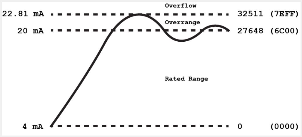
Our normal range or nominal range is 4-20mA. But above and below that, some extra mA is usually added to the range. They divide the upper range into these two categories:
• Overshoot range (overrange)
• Overflow
And the lower range in these two:
• Undershoot range (underrange)
• Underflow
What this means is that, instead of a 4-20 mA range, we now have a range of 1.185 - 22.96 mA. The same applies to other types of analog signals. For example. the range from 0 to 10V is from 0 to 11.852 V. All of this means that our analog signal ranges can be illustrated like this:
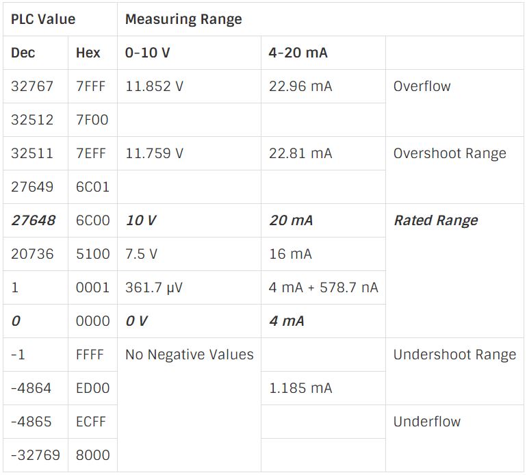
With overflow and underflow in mind, we can now start calculating the actual resolution of our analog signal. But instead of just using the 22.96-1.185 mA or 11.852 V ranges, there is a number that you should note here: 27,648.
As you can see in the table above, this is where our classified range ends. Our resolution for a 0 to 10 V signal must therefore be calculated as follows:
10 V / 27648 = 361,7 μV
Or for our 4-20 mA signal:
16 mA / 27648 = 578,7 nA
These two numbers are the minimum values that we can represent in the CLP with the digital value. In most cases, these measurements are small and accurate enough. Also remember that the higher resolution you want, the more expensive the PLC analog input and output modules.
Analog Inputs
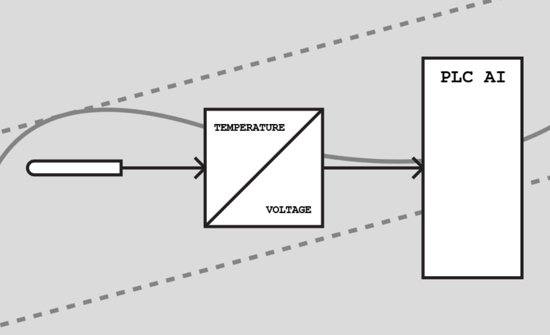
Analog inputs can come from a variety of sensors and transmitters, or both. For example, one of the types of thermocouples connected to a transmitter, which is then connected to an analog input on the PLC. You can measure a lot of different things. The job of the sensor or transmitter is to turn this into an electrical signal. Here are some of the things you can measure with analog sensors:
• Level
• Flow
• Distance
• Viscosity
• Temperature
• Pressure
The main point is that the sensor or the transmitter turns the physical values into an analog signal. It is this signal that we can use on the PLC as an analog input.
An example here could be a temperature transmitter with a 4-20 mA output. Connected to the transmitter is a temperature sensor. The transmitter is then calibrated to a range of 0-100 degrees. What this means is that when the temperature is 0 degrees, the transmitter's output will be 4 mA and 20 mA per 100 degrees.
A transmitter is often necessary because the sensor itself cannot provide us with an analog signal. Or at least not one that fits the PLC's analog input. It is possible to buy analog input modules where you can directly connect a temperature sensor. But, most of the time, you will have a voltage or current input module to which you will connect a transmitter.
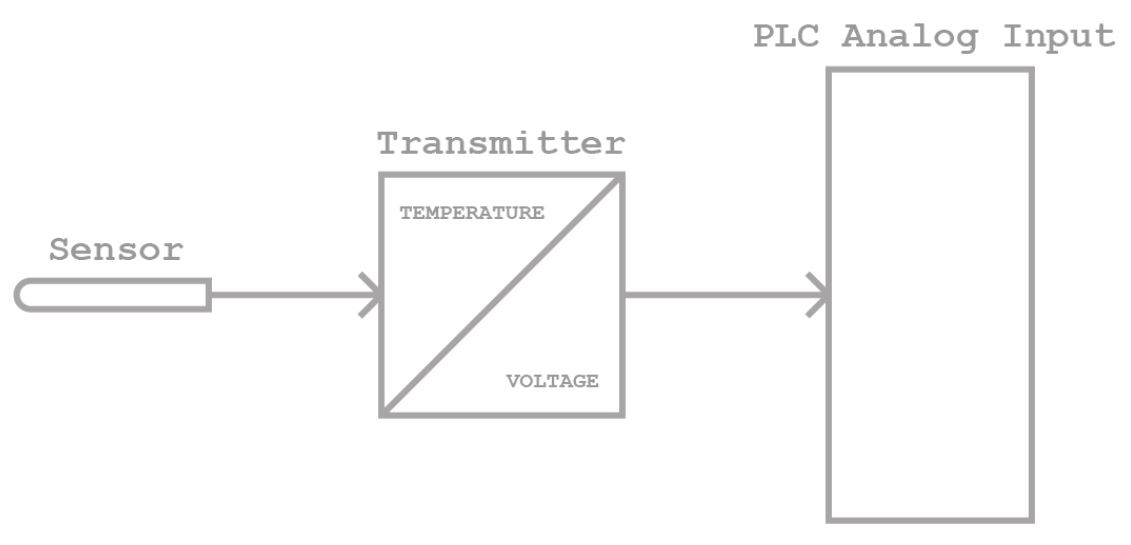
Calibration is very important when talking about transmitters. You need to know how much these mA or volts represent in the physical value.
Analog inputs wiring
Analog voltage input wiring
The use of voltage for analog signals is quite common. They are also quite easy to connect, as you usually only need two wires. But that does not mean that you should not be careful when connecting this type of analog signal. If it is not connected correctly, you may get a defective analog signal or, worse, a damaged analog input module.
Therefore, basically all analog voltage inputs have two terminals:
• AGND: The ground or reference for analog inputs
• AIN: Analog input
The tension is always measured between two points. You cannot take a point and then say: at this point I can measure 10 volts. For that, you need a point of reference. Like a battery. A 9-volt battery has only 9 volts between the positive and negative sides.
That's why we use AGND or analog ground. It is between AGND and AIN that the PLC measures how many volts there are at the analog input. It also gives us the answer to what AIN is.
When you are connecting the analog voltage source, the AIN is where you connect the positive (+) side of it. The negative side (-) must be connected to the AGND. These are the two main wires of the analog signal.
But if you connect only these two, you will have a very vulnerable signal. Electromagnetic compatibility (EMC) can easily change the analog signal.
As you can see below, this is resolved by protecting the wires and connecting the shield to the ground. Be aware that this is NOT the same ground as AGND!
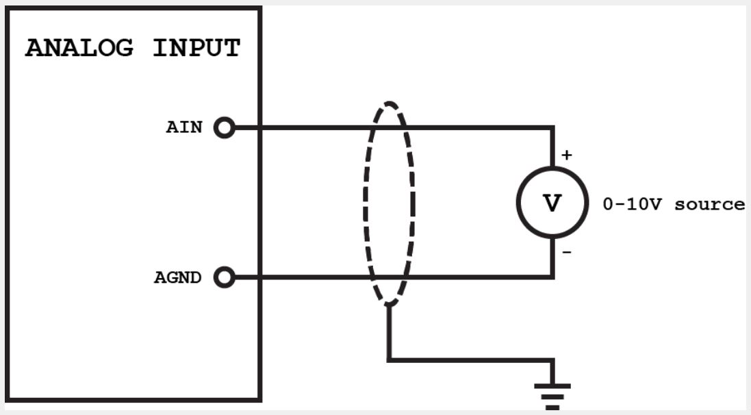
The fact is that not all lands are equal. Where AGND is used as a reference for our analog signal (0 volt), the shield must be connected to earth. Because the noise is really just current induction in the wires because of the magnetic fields. Using a shield, the current will be induced in the shield, instead of the wires of our analog signal. This current needs to be removed and that is why we connect the shield to the ground.
Voltage drop in wires
As we are dealing with voltage here, there is something in the wiring itself that can cause problems. All electrical wires (conductors) have resistance and therefore create a voltage drop. This can potentially mean that the voltage at the analog input is different from the voltage at the transmitter. Obviously, this only has a significant consequence if you have long wiring distances or very small wires.
Current analog input wiring
Instead of voltage, you can also use the current as an analog signal. They may be a little more difficult to connect, but in general they are more stable. Especially one of them has a very smart feature that probably makes it the most used type of analog signal.
The current in the analog signals is usually measured in milliamps (mA). A typical range here is between 0 and 20 mA. Less than that would be difficult to measure and more than that would soon become dangerous.
Let's take a look at what it really means to use current in analog signals.
First of all, you need a closed loop for the current to flow. Although the wiring for the first type of current transmitter is the same as the voltage, something different happens here. Current is the flow of electrons from one pole to another. That is why you will always need a closed circuit to measure the current.
Resistor Shunt
In fact, the PLC cannot even measure the current. So what happens is that, inside the analog input module, a resistor is placed between the positive (AI) and the negative (AGND). This not only makes up the closed circuit, but also converts our current signal into a voltage signal.
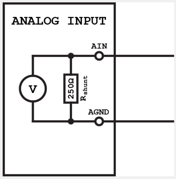
The resistor is called a shunt resistor and has a specific resistance. In some analog input modules it is 250 Ohm, for example. And, due to Ohm's law, the analog current signal can now be converted into a voltage signal by simple calculations.
Voltage (V) = Resistance (R) x Current (I)
As we have a well-known resistance of 250 Ohm, it is also possible to calculate how many milliamps our measured voltage corresponds to. With this scenario in mind, let's take a look at the wiring of the analog current inputs. They can generally be divided into three types:
• 2-wire analog input
• 3-wire analog input
• 4-wire analog input
When talking about 2, 3 and 4 wires, what we are talking about here are actually the transmitters or transducers. Current transmitters can be connected in different ways and therefore with a different number of wires. The difference is actually the signal power supply. Sometimes the transmitter will power the circuit and sometimes you will need to use an external source.
2-wire analog input
The first and simplest way to connect a 2-wire transmitter is to connect it to the loop supply. Basically, this means that the PLC will supply the current loop. Only 2 wires are needed here. For the PLC to supply the current, we need to use another terminal on the analog input module:
A+: Analog input source
A wire that passes from A + through the transmitter and back on another wire to AIN. The source comes from A +, the transmitter controls the current flow and the analog current signal enters AIN.

You can also use an external power supply for the 2-wire transmitter. Connect 0 V from the source to the AGND and 24 V through the transmitter back to the AIN. Although you practically need 3 wires for this, it is still considered a 2-wire analog input connection, because the transmitter has only two wires.
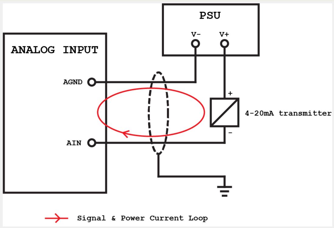
A disadvantage of 2-wire current loops is that you only have one loop for the power and signal. In fact, this means that the transmitter needs to draw less than 4 mA to function. Some sensors and transmitters consume more than that, which leads us to 3 and 4 wire loops.
3-wire analog input
In a 3-wire current circuit, only the ground is shared between the source and the signal. The ground is connected to the AGND and the power supply (-). The transmitter has 2 positive wires (+). One that goes to the power supply (+) and the other to AIN.
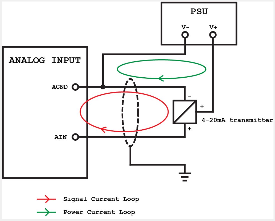
Although they share the ground, a 3-wire transmitter creates 2 loops. One for the signal and the other for power. The sensor or transmitter can now consume the required amount of current without interfering with the analog signal.
4-wire analog input
The 4-wire transmitter is also widely used, as it separates the power supply from the signal. When supplying the transmitter with 4 wires, you can have 2 for the power and 2 for the signal. Naturally, the 4-wire transmitter requires an external power supply.
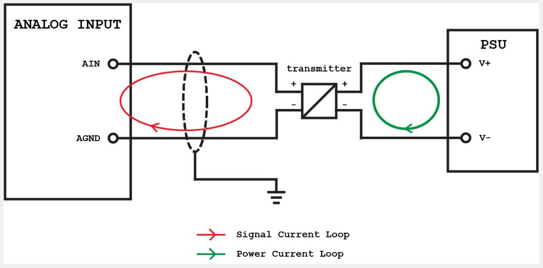
Clearly, the biggest advantage of using a 4-wire transmitter is the complete separation between power and signal. They can be totally isolated or opto-isolated, so that the disturbance in the feeding does not affect the signal.
Analog input scale
When the analog input signal enters the PLC, you often need to scale it up in your PLC program. What the scale means is that you convert the raw value of the analog input into some kind of engineering value. An engineering value is a number that represents the physical value, for example flow (m3/s), weight (kg) or temperature (degrees).
Conversion or escalation is done simply with a few accounts. Some software (IDE) even have a functional block specifically for scheduling.
Scaling with math
The analog signal becomes a raw value in the PLC, but that number actually represents nothing but, for example, a number between 0 and 27648. What the analog signal represents is a physical measurement like 0 to 300 degrees. It will often be necessary to work with the engineering value in our PLC program or to show the measurement on an HMI.
Somehow, we have to convert the range 0-27648 to 0-300.
Mathematically, we can describe it with this relationship:
Gross Value / 27648 = Engineering Value / 300
By isolating the value of engineering, we now obtain an equation that we can use directly in our PLC program. This equation can be used to scale the analog input to the engineering value:
Engineering value = (Gross value / 27648) * 300
Analog Outputs
Analog outputs have many similarities to analog inputs. However, there are still some differences in the way you connect them and the way you use them in your PLC program. Analog outputs can be divided into two types:
• Voltage
• Current
Or we use voltage or current as an analog signal.
Analog outputs wiring
No matter what type of analog output you are using, there is always one thing to keep in mind. Load. Because you will essentially connect a load to the output. It can be a flow control valve, a frequency inverter or even an analog input in another PLC.
The device you connect to your analog output is the one that decides what type of analog signal you should use. If you want to control a valve with a 4-20 mA signal, its analog output must also be 4-20 mA.
oltage analog output wiring
Again, the analog voltage output is the easiest to connect. For this, you will only need 2 wires. A positive and a negative side of the voltage source. See how a simple 2-wire analog voltage output is connected:
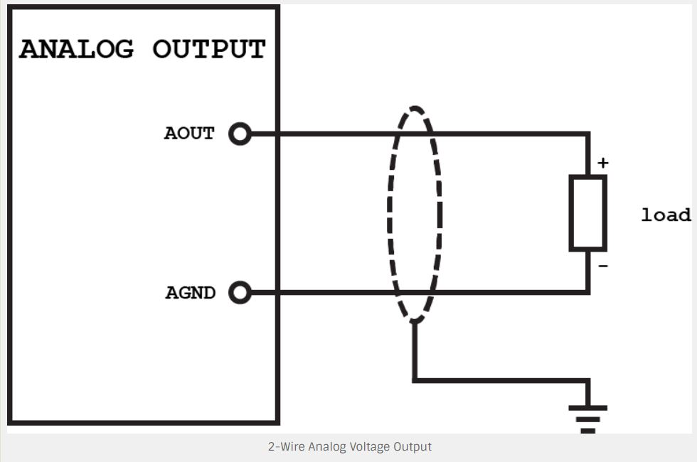
But sometimes 2 wires are simply not enough even for voltage outputs. Some analog output modules have two extra terminals on their analog outputs. They are used to compensate for something called line impedance or resistance. Impedance is the opposition that a circuit presents to changes in current or voltage. Since we are dealing with tension, any resistance will create a voltage drop.
If you have an analog voltage signal that changes the resistance, it is even greater. These two additional wires exist to compensate, so that the voltage level at the analog output is the same as the voltage level at the destination.
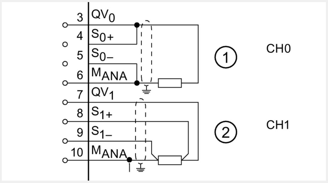
Talking about resistance, there is also something else you should be aware of when dealing with analog voltage outputs: load impedance. To avoid a short circuit on the analog output, the load connected to the output must have a minimum load impedance. This is usually between 500 and 1k Ohm.
Current analog output wiring
Most analog outputs on the PLCs function as a 3-wire transmitter. This may seem strange, since we only had 2 wires so far. But the PLC usually provides an internal power supply, giving us the third wire. The power for the signal.
This means that when you are working with current outputs, most of the time you only need to connect the current loop of the signal. You will also need to connect the power circuit. But this is usually necessary to power the module itself so that the PLC can see it.
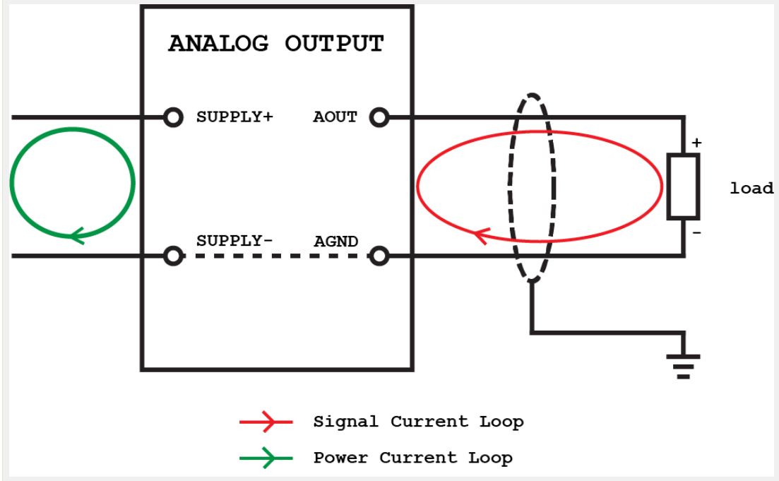
A big difference between the current and voltage outputs is the load impedance. Voltage outputs require a minimum load impedance, whereas for current outputs, the maximum load impedance must be checked. Remember, we are talking about the current flow here and the impedance (resistance) limits the current. If the load impedance is too large, the loop simply cannot direct the required current flow.
A typical PLC analog current output has a maximum load impedance of 300-500 Ohm.
Scaling analog output
If you know how to scale an analog value, you also know how to "de-scale". Because this is something that you often need to do. "De-scaling" means turning the engineering value into a value that the module can convert into an output.
Let's say we have an analog 0 to 10 V output signal to control the speed of an engine. To start the engine at 50% speed, we need to generate a 5 V analog signal at the output. To do this, we need to know what value to send to the D/A converter. In other words, we need to know our range.
For example, we can use a range from 0 to 27648.
As we now know our range, we can calculate 50% of that: 13824.
The problem here is that the operator does not insert 13824 into the HMI as a setpoint. What it will normally define is the engineering value, in this case, percentage (%). That is why we now have an engineering value that we need to convert to a value within the analog output range.
You can resize it in two different ways. With math or function blocks. Using math is a good way to make it easier to understand what's behind. Just use the same relationship with the scale:
Gross Value / 27648 = Engineering Value / 100
When isolating the gross value, you now have a mathematical expression for converting an engineering value to a gross value. You can implement this in structured text with just one line of code:
Gross Value: = (Engineering Value / 100) * 27648;
Next Unregistered user. Buy the training at jats.com.br.