SIEMENS SIMATIC S7 + WINCC
SIMOCODE pro
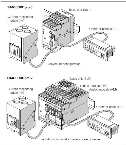
SIMOCODE pro (SIRIUS Motor Management and Control Devices) is a motor management and equipment control system with a Profibus DP interface. It is flexible, modular and has all the necessary functions of an motor feeder.
SIMOCODE pro can be subdivided into two series of equipment with different functions:
• SIMOCODE pro C – compact system for direct and reversible starts;
• SIMOCODE pro V – offers additional functions to SIMOCODE pro C, such as star-delta start, soft start.
The motor can be controlled:
• locally: control station - local control (LC) for manual on/off switching;
• panel door: control station operator panel (OP) for manual on/off switching;
• in automation level: control station PLC/DCS (DP) for remotely controlled on/off switching via Profibus DP.
• via SIMOCODE through internal logic modules.

The following diagram shows the configuration of the SIMOCODE pro with its external inputs and outputs and internal function blocks:
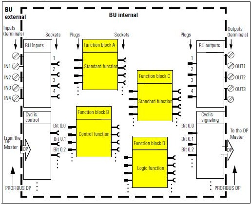
The control commands can be:
• motor on (ON>), motor off (OFF) for a direct starter;
• motor left (ON<), motor off (OFF), motor right (ON>) for a reversible starter;
• motor slow (ON>), motor fast (ON>>), motor off (OFF).
Control stations
• local control:
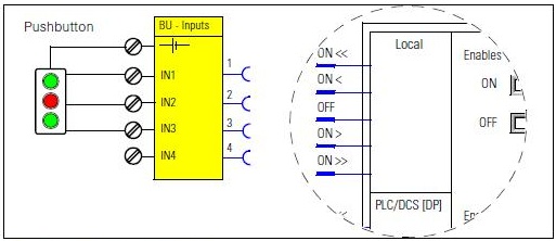
• PLC/DSC – via Profibus-DP telegram with cyclic control:
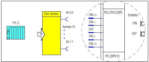
• PC (maintenance) – via Profibus-DPV1 telegram of acyclic control (softwares SIMOCODE ES / PDM). The PC enters as a second Profibus-DP master in the network.
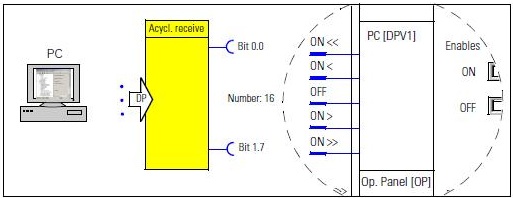
• Operator panel:
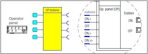
Modes of operation and mode selectors
It is possible to use the control units individually or together. There are four different modes of operation that can be switched:
• Local 1;
• Local 2;
• Local 3;
• Remote/Automatic.
The modes are used to switch the four transition modes. Plugs S1 and S2 are combined to select operation mode:

Cyclic send
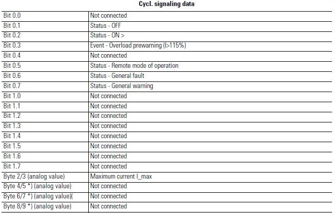
The "Cyclic signaling" function blocks are used to determine what information is cyclically provided for the automation system via Profibus DP.
The "Cyclic signaling" function blocks consist of:
• 8 bits each (2 bytes, byte 0 and byte 1 for binary information);
• 4 words (= 8 bytes, byte 2 to byte 9 for four analog values, freely parametrizable).
• 1 output each for Profibus DP.
In total there is 3 function blocks "Cyclic Send" (0, 1, 2/9).

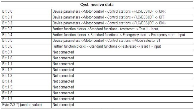
The cyclic data is exchanged for each DP cycle between the DP master and the DP slave. The DP master sends cyclic control data to the SIMOCODE pro. In response, the SIMOCODE pro sends the cyclic send data to the DP master.
Transferring data
Data transfer options:
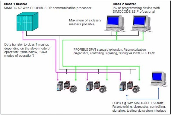
Principles of communication
The image below shows the principles of communication in which different types of data are transferred according to the master and slave management modes.
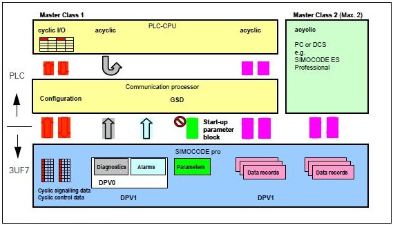
Telegrams
• Cyclic data from the Profibus DP master to the SIMOCODE pro:

• Cyclic data of the SIMOCODE pro to the Profibus DP master:

The content of the cyclic data (digital/analog information) can be parameterized via SIMOCODE ES software.
Basic configuration for direct starter:

Basic configuration for reversible starter:

Boiler Project
• Create Function Block for Simocode direct start. Right-click on the Blocks folder and select Insert New Object > Function Block menu item.
• Set Symbolic Name to FB_SIMOCODE, Symbol Comment with Function Block Simocode Direct Start and the language to LAD.
• Open function block FB5 FB_SIMOCODE for editing. In Component View, double-click on the function block.
• In Interface, enter the IN input parameters:
| Name | Type | Description | S7_m_c |
|---|---|---|---|
| YC | Bool | FB_Motor command | |
| YS_I0_2 | Bool | Status – ON > | |
| OV_I0_3 | Bool | Event - Overload prewarning (I>115%) | |
| GF_I0_6 | Bool | Status – General fault | |
| GW_I0_7 | Bool | Status – General warning | |
| II_IW2 | Word | Current | |
| FATOR_II | Real | Fator Current setting | |
| RST | Bool | Reset alarms | |
| NO | Int | Profibus-DP address | True |
• Enter the OUT output parameters:
| Name | Type | Description | S7_m_c |
|---|---|---|---|
| YC_Q0_1 | Bool | OFF command | |
| YC_Q0_2 | Bool | ON> command | |
| RST_Q0_6 | Bool | Reset | |
| SO | Bool | Event - Operation overload (I>115%Is) | True |
| FG | Bool | Status – General fault | True |
| AG | Bool | Status - General alarm | True |
| SON | Bool | Status - On | True |
| CORRENTE | Real | Motor current | True |
• Enter the STAT parameters:
| Name | Type |
|---|---|
| XI | Int |
| XDI | DInt |
| AUX | Real |
• Insert logic for Simocode.
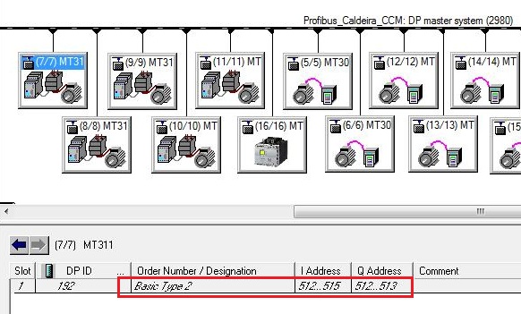
The SIMOCODES in the project were defined with Basic Type 2 telegram, with 4 reading bytes (coming from SIMOCODE) and 2 writing bytes (going to SIMOCODE).
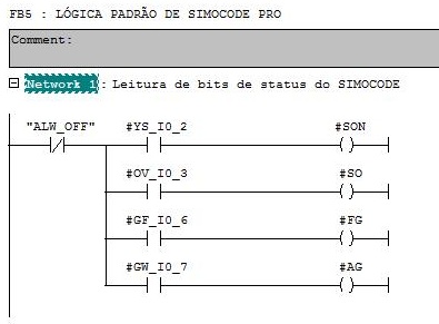
Network 1
Movement of SIMOCODE status bits to the supervisory.
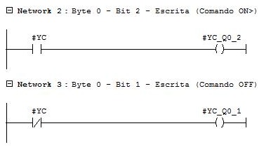
Networks 2 and 3
Run (ON>) and stop (OFF) motor command.
Network 4
Reset SIMOCODE fault.

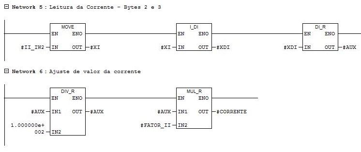
Networks 5 and 6
Current setting for real value (Word range 0 ... 65535 and unit 1%/Ie). Insert value in parameter FATOR_II calculated according to the configured maximum current Ie.
• Create Function for FC3 MOTORS engines. Right-click on the Blocks folder and select Insert New Object > Function menu item.
• Open MOTORS function and insert FB_MOTOR and FB_SIMOCODE for the MT306 motor - Ash Removal Thread.
| Name | Block | DB | Input | Output |
|---|---|---|---|---|
| MT306 | FB_MOTOR | DB19 | ||
| MT306SIM | FB_SIMOCODE | DB20 | IW528..531 | QW520..521 |
Network 1
Function block instance FB_MOTOR for MT306. Response time for activation and deactivation in 5 seconds.

Networks 2 and 3
Movement of motor status running SON = 1 and motor stopped status SON = 0 from MT306SIM to MT306.

Network 4
Force parameter BLQ to 1 to enable the motor to start.

Network 5
Function block instance FB_SIMOCODE for the MT306 motor.
Input parameters:
YC – receives the YC output parameter from the MT306 function block instance.
YS_I0_2 – status ON> - receives the read address byte 0 bit 2 of SIMOCODE (byte 0 = 528).
OV_I0_3 – overcurrent - receives the reading address byte 0 bit 3 from SIMOCODE.
GF_I0_6 – general fault - receives the reading address byte 0 bit 6 from SIMOCODE.
GW_I0_7 – alarm - receives the reading address byte 0 bit 7 from SIMOCODE.
II_IW2 – current - receives bytes 2 and 3 from the SIMOCODE reading (byte 2 = 530).
FATOR_II – current adjustment (value to be calculated. Ex = 10).
RST – alarm and fault reset.
NO – Profibus DP address (address 11 for MT306).
Output parameters:
YC_Q0_1 – OFF command - write to the SIMOCODE byte 0 bit 1 write address.
YC_Q0_2 – ON> command – write to the SIMOCODE byte 0 bit 2 write address.
RST_Q0_6 – reset – write to the SIMOCODE byte 0 bit 6 write address.
FG – general fault - writes to the FAULT input parameter of the MT306 function block instance.

Network 6
Reset of the alarm acknowledgment button activated by the operator.

• Make the call to FC3 MOTORS in OB1.
• Select Operator Control and Monitoring for DB19 and DB20 of the MT306 motor.
• Compile AS and OS.
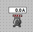
• Create motor representation objects.
• Create SIMOCODE.pdl with 400 x 200 size.

• Insert custom object for MT306 in the process picture.
C script to show the picture window object PW_OBJ in the current picture.

The Picture Name property of the picture window PW_OBJ receives the name of the SIMOCODE.PDL picture.
The TagPrefix property of the picture window PW_OBJ is defined as CALD/MT306. This instruction adds the text “CALD/MT306” at the beginning of all dynamizations of objects within the picture window.
• Insert MT306 engine alarm messages in WinCC Alarm Logging.
• Compile and download AS. Compile OS and run the project. Test motor.
•Repeat the procedure for the other SIMOCODES:
| Name | Block | DB | Input | Output |
|---|---|---|---|---|
| MT311 | FB_MOTOR | DB21 | DP address = 7 | |
| MT311SIM | FB_SIMOCODE | DB22 | IW512..515 | QW512..513 |
| MT312 | FB_MOTOR | DB23 | DP address = 8 | |
| MT312SIM | FB_SIMOCODE | DB24 | IW516..519 | QW514..515 |
| MT313 | FB_MOTOR | DB25 | DP address = 9 | |
| MT313SIM | FB_SIMOCODE | DB26 | IW520..523 | QW516..517 |
| MT314 | FB_MOTOR | DB27 | DP address = 10 | |
| MT314SIM | FB_SIMOCODE | DB28 | IW524..527 | QW518..519 |
• Insert motors in the Soot Blowing picture.