Server-client Architecture
Multiproject
Dividing the multiproject into functional units is recommended in principle in PCS 7 (e.g. one project per unit). This setup provides the maximum flexibility during the configuration and commissioning phase. This applies in particular to automation systems (AS). This way the configuring engineer responsible for one or more automation systems (AS) can, for example, uncouple the appropriate project from the multiproject and configure this project separately.
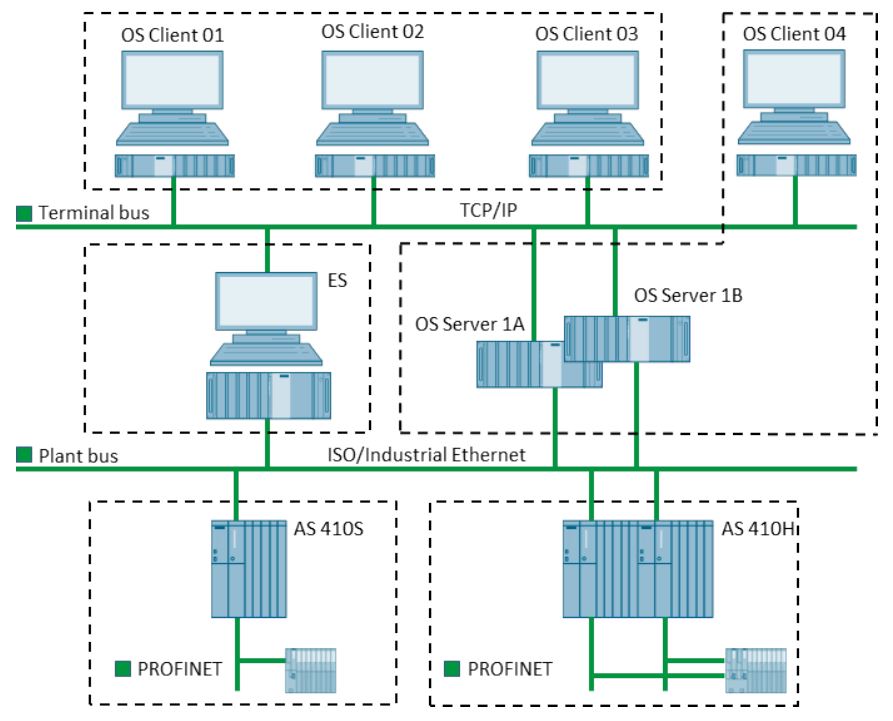
The multiproject ("Comp_MP" in the following example) should consist of the following parts:
• Project "01_PLANT_A" for a unit consisting of fault-tolerant AS
• Project "02_PLANT_B" for a unit consisting of standard AS
• Project "25_ES" for one or more engineering stations
• Project "20_OS" for the redundant OS server pair and an OS client
• Project "21_CL", for OS clients of the same type as typical operator stations
• Master data library "Comp_Lib"
The division of the multiproject into various projects is determined by technological and local circumstances, as well as by specific project factors, such as the number of project engineers or the delineation of responsibilities.
When PROFINET is used, it must be ensured when dividing the multiproject into individual projects that all stations that share a PROFINET network are in the same project. The functions of HW Config, e.g. topology configuration (automatic commissioning), can then be used.
A redundant OS server pair must always be created in the same project. Referenced operator stations must be created in the same project as the reference.
Once the projects are created the corresponding structure is displayed in the component view of the SIMATIC Manager.


OS Server
The following steps show you how to insert and configure OS servers in the project:
1. Insert a new PC station into the subproject "20_0S" by selecting the project and selecting the "Insert New Object > Preconfigured Station ..." via the shortcut menu. The PCS 7 Wizard executes.

2. Click "Next" without selecting a CPU.
3. Select the "PCS 7 OS" option box and the "Multiple station system redundant" option.

4. Terminate the PCS 7 wizard. The following structure is created in the component view for project "20_OS":

5. Rename the three new PC stations. The names "SERVER1A", "SERVER1B" and "CLIENT01" are used in the example project "Comp_MP".
6. Change the name of the OS object of station "SERVER1A" to "OS1".
7. Open the properties dialog of the "OS1" and click on the "Target OS and Standby OS" tab.
Make the following settings:
• Enter the path for the target OS computer. A shared folder with write access must be available on the target OS.
• Enter a meaningful name for the symbolic computer name. The symbolic computer name determines the server prefix and therefore the server data. It is decisive for the OS server-client communication. Avoid any special countryspecific characters with this. This setting can only be entered with the initial configuration.
• Select "OS1_Stby" from the selection menu in the "Standby OS" area.
• Select the "Transfer to external archive server" check box if necessary.
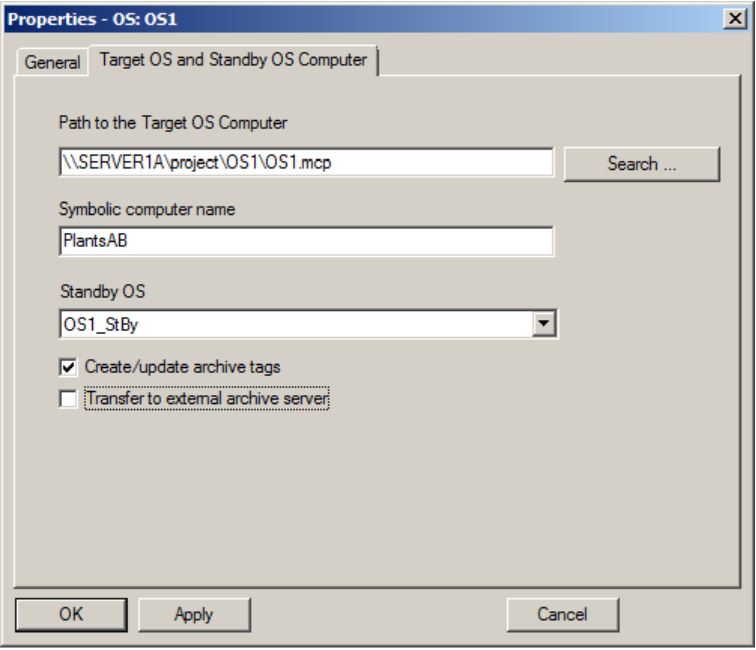
8. Open the properties dialog for the assigned standby OS and enter the path for the corresponding target OS computer here as well.
9. Open the SERVER1A configuration dialog and configure the CP1623 as a network adapter for the system bus in a free row. Use unique MAC addresses for this and assign a subnet with the name "Plantbus".
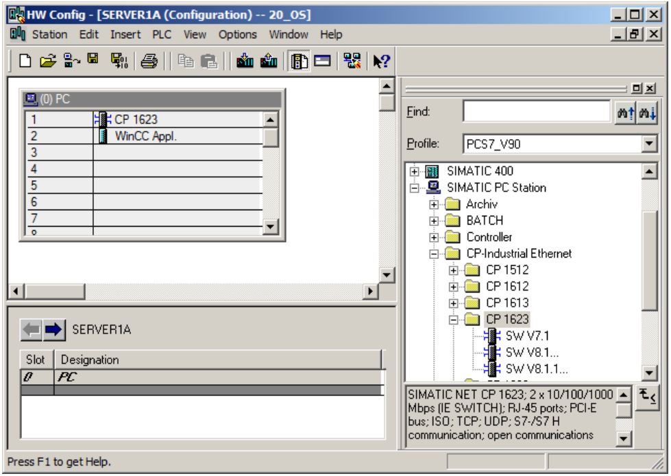
10.Select time of day mode in the "Options" tab of the CP1623 properties dialog.
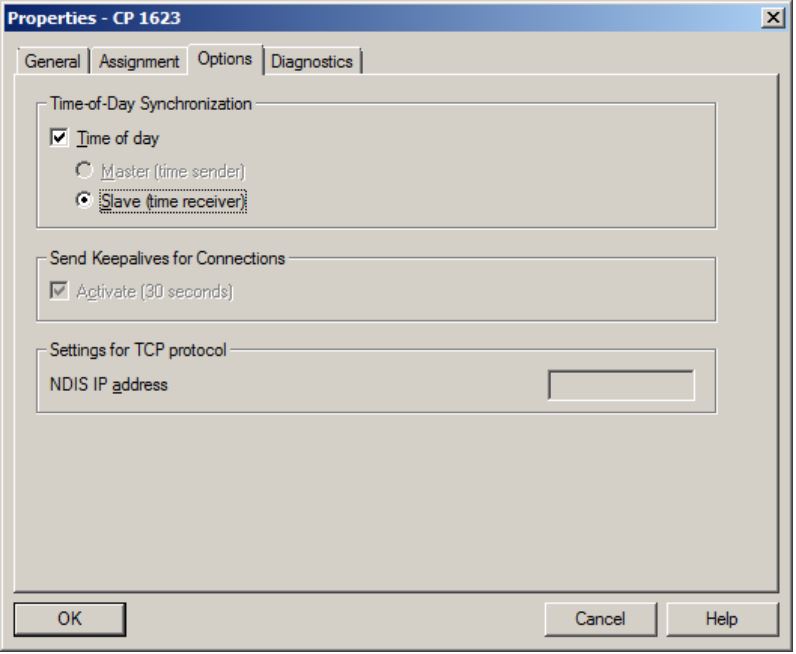
11.Configure SERVER1B in the same way as SERVER1A.
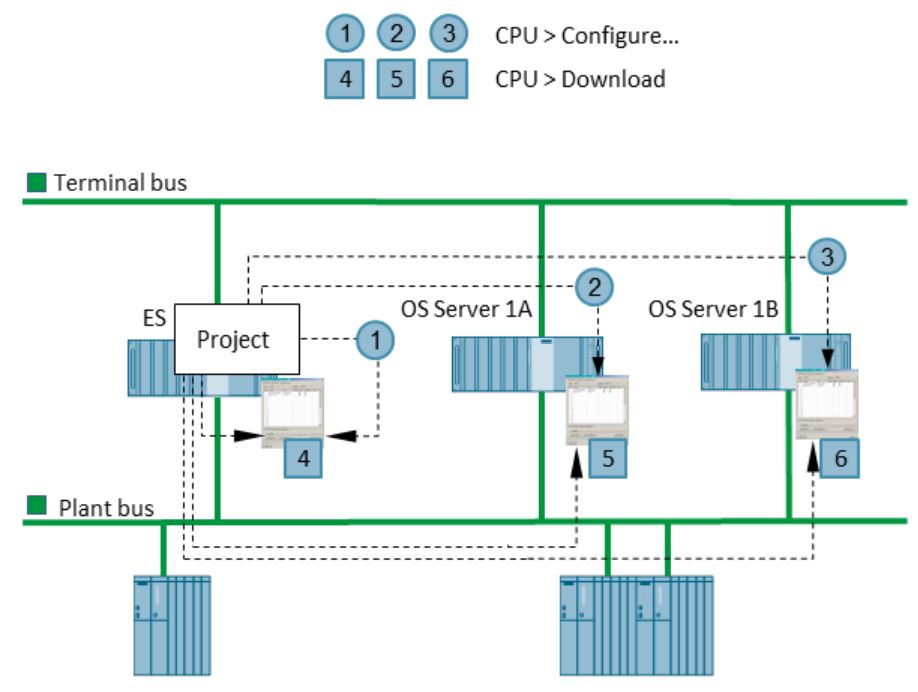
12.Transfer the PC station configurations from the SIMATIC Manager to both the OS servers via the "PLC > Configure …" command.
13.Load the configuration via the "PLC > Download…" command in the program. The following figure illustrates the configuration of the system bus, whereby all tasks are performed from the central ES.
OS Clients
By creating the stations in the project "20_OS" an OS client station has already been created which was renamed to "CLIENT01" in the previous section.
This OS client can be configured and started accordingly in the later configuration stages. Furthermore the connection to OS servers already activated can also be tested.
The OS clients for the plant operator are created later once the configuration is complete in the separate project "21_CL".
The following steps demonstrate how to create the station "CLIENT02":
1. Copy the completed station "CLIENT01" from project "20_OS" to project "21_CL" and rename it to "CLIENT02".
2. Rename the OS client project in the SIMATIC Manager as "CL02".
3. Enter the path for the target OS in the object properties.
A shared folder with write access must be available on the target OS. OS reference clients are always used when all settings on several OS clients are identical. Each configured OS client can be used as a basis for further clients. Creation and maintenance efforts along with the project scope for operator stations are reduced considerably as a result.
In the example project, the stations "CLIENT03" and "CLIENT04" should be identical to station "CLIENT02".
The following steps demonstrate how to configure the stations "CLIENT03" und "CLIENT04":
1. For the number of identical clients configure a PC station for each with "WinCC Appl. Client Ref".

2. Configure the OS basis and the path to the target OS computer in the object properties of the OS project created within "WinCC Appl. Client Ref". A shared folder with write access must be available on the target OS.
3. Select the appropriate project from the existing OS client projects in the "OS Basis" field.
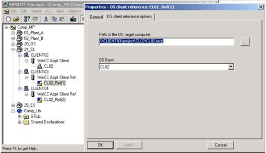
The station "CLIENT03" is identical to station "CLIENT02" in project "Comp_MP". In this case the OS project "CL02" can be used as a basis for station "CLIENT03". The path to the target OS computer is set on the station "CLIENT03".
If the settings for a referenced OS client change in relation to the base client, a new base client must be created.
Requirements for WinCC in Distributed Systems
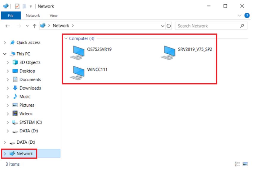
First of all, check whether the WinCC stations involved are displayed to each other in the Windows network. To do this, open Windows Explorer (shortcut: Windows key + E) and select or open "Network" at the bottom. The names of the computers to be reached must be displayed without further action. Especially if this is not the case, you must check all the following points and adjust them if necessary. Then test the display of the computers in the network again.
To configure the Simatic Shell, open the relevant workstation in Windows Explorer ("This PC") and double-click the "Simatic Shell" folder in the "Devices and drives" area. Right-click "Simatic Shell" and select "Settings..." from the shortcut menu.
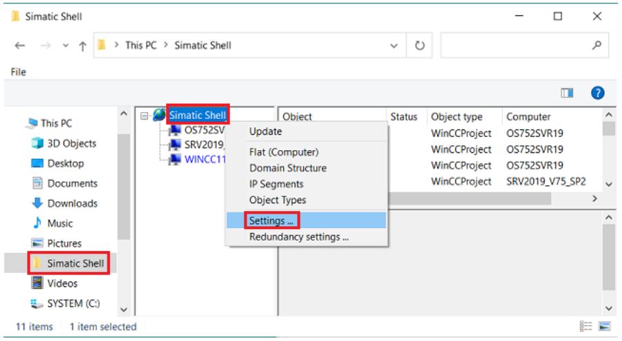
With WinCC V7.5 or higher, you must enable "Remote Communication" here.
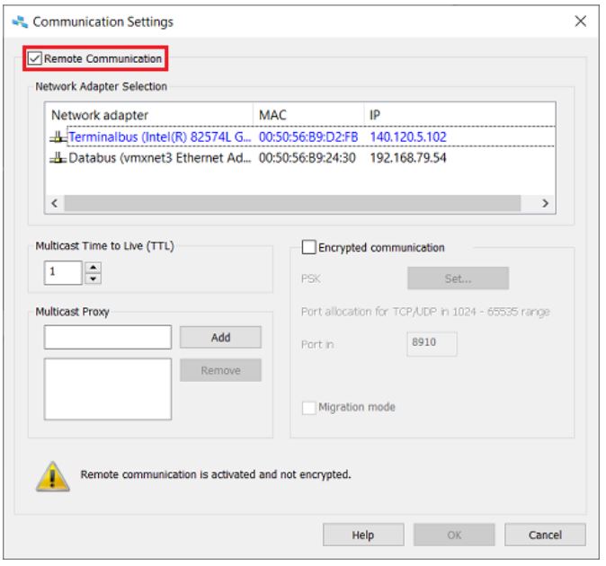
When you first enable "Remote Communication", you will be prompted to enter a password for "Encrypted Communication" in a separate window.
If this window does not open automatically, you can open it manually using the "Set..." button. You can also use this to change the password at a later date.
The security key must be identical on all computers so that the participants can see and communicate with each other.
You can identify the network card currently set for the WinCC terminal bus by the blue font.
Make sure that the terminal bus in the Simatic Shell is configured for the network card currently being used for WinCC communication. This ensures that the Simatic Shell addresses the correct network card for communication if a computer has multiple network cards.
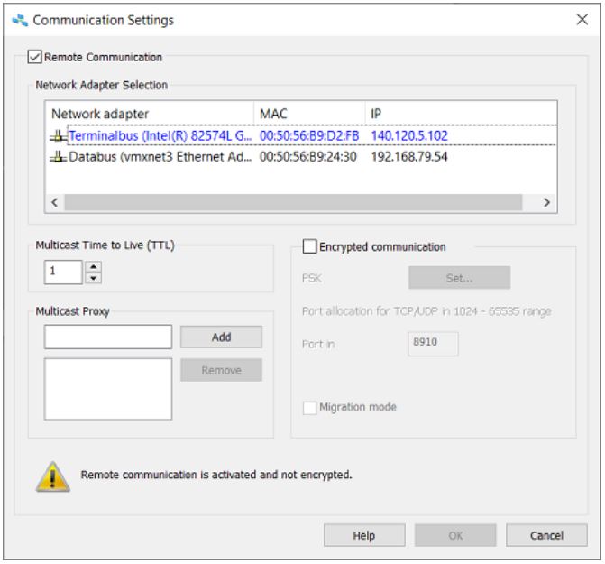
Adjust the "Multicast Time to Live" according to your network architecture.
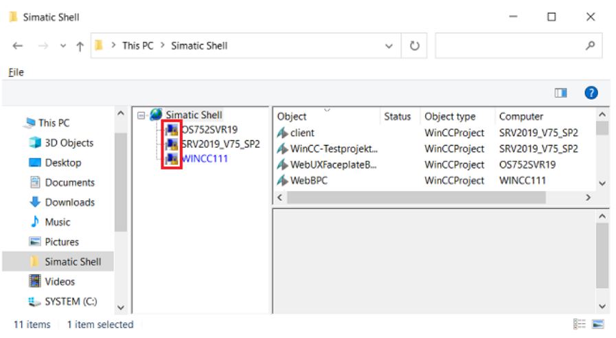
You can tell that the network is configured correctly by the fact that the computers concerned and their WinCC projects are listed in the "Simatic Shell". The yellow locks on the computer icons indicate that the communication is encrypted.
For redundant WinCC servers (Redundancy option is activated), you require three network cards on both servers:
Terminal bus = connection WinCC client-server stations, including WebNavigator as well as OPC
Plant bus = connection WinCC with PLC (also for Modbus TCP/IP)
Redundancy bus = connection Master to Standby
The PG/PC interface must not be set to "Auto"!
Lmhosts
Configure the name resolution of the computers for the terminal bus using the "lmhosts" file.
To do this, the lmhosts file must be located in the path "C:\Windows\System32\drivers\etc" on Windows systems.
There you will find an inactive template with commented explanations and examples under the name lmhosts.sam (the file extension ".sam" stands for "Sample File"). Change the name of this file to "lmhosts", without file extension!
Here is an example of the configuration of the lmhosts with three registered computers:
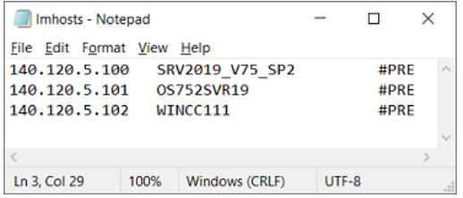
lmhosts is used in Windows workgroups to resolve computer names. It therefore fulfills the same task as the hosts file in domain networks. If you are operating a local network, configure the lmhosts file. Otherwise, in domain networks, change the hosts file.
Windows User Settings
Make sure that the following is fulfilled in the user settings:
1. The Windows user with whom you are logged on to the Engineering Station (ES) is also known on the Operator Station (OS). The user has the same user name and the same password.
2. A password has been assigned.
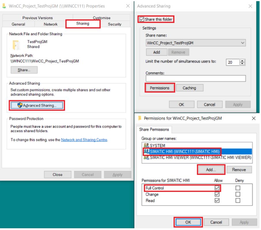
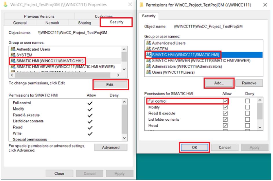
3. You have sufficient authorization for the target folder of the OS. Use the Windows Explorer of the ES to test whether you can create any file on the target folder of the OS. If this fails, you have to assign the corresponding permissions. For this you right-click the folder into which you want to load the project. Click "Properties". Switch to the "Sharing" and "Security" tabs. If not yet available, add the "SIMATIC HMI" group and assign full access rights.
4. User administration
The user is a member of the "SIMATIC HMI" group on OS and ES and has at least the status "Power User".
If ES and OS are in the same domain, the domain account must be entered in the "SIMATIC HMI" group on both computers.
The "SIMATIC HMI" group is a local group. To check this, right-click "Start" and select "Computer Management".
Click "Local Users and Groups" and then double-click "Users". Double-click the user you want to use to load the project. Switch to the "Member Of" tab.
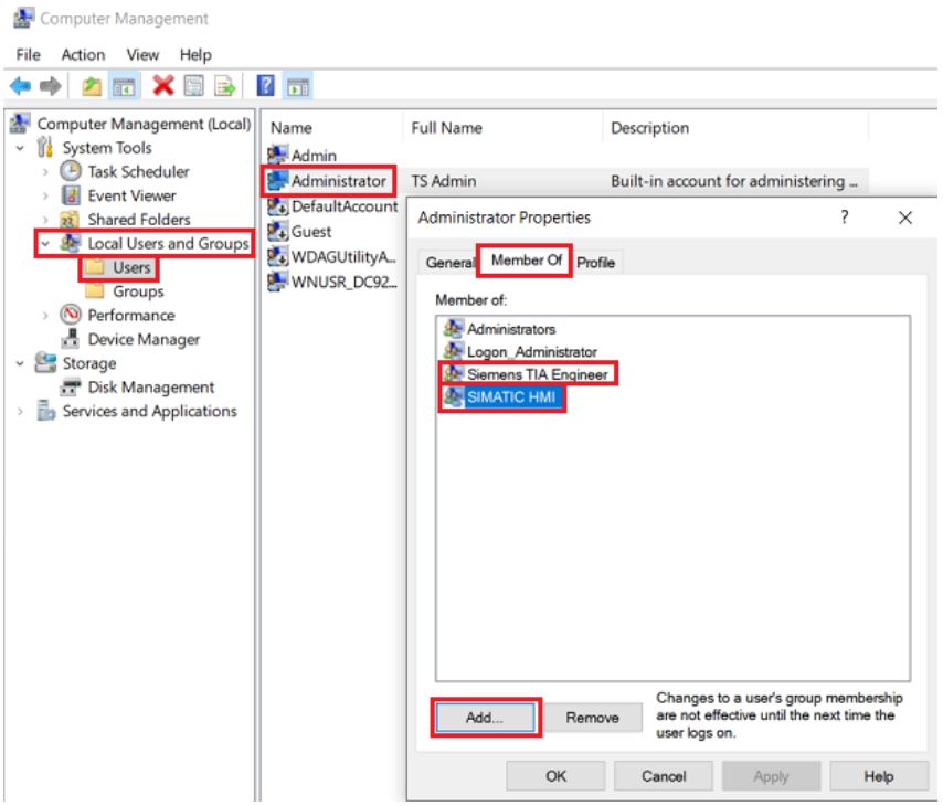
You can use the "Add..." button to add user groups.
Workgroup/Domain
All SIMATIC WinCC stations must either be logged into the same workgroup or the same domain (mutually trusted domain).
You can customize the membership of a computer to a domain or workgroup under "Control Panel > System and Security > System" in the "Computer name, domain, and workgroup settings" area.
Windows Groups
All users of a computer using WinCC must be able to authenticate each other (same user + password). For this, all local users must be members of the Windows group "SIMATIC HMI". This Windows group is created automatically when WinCC is installed.
You can find the groups by navigating to "Administrative Tools > Computer Management > Local Users and Groups > Groups" in the Control Panel.
To ensure that a client can successfully access the WinCC project on the server, you must also create the client users as users on the server and add them to the Windows group "SIMATIC HMI". Make sure that the user name and password of the user are identical on the client and on the server.
Firewall Settings
To enable WinCC computers from different networks to communicate with each other, you must change the settings of the local Windows firewall.
For all WinCC-specific firewall rules, you must add the range with the IP addresses of the computers from the other networks or the complete IP range of the other networks.
1. In the Windows Control Panel, open the category "System and Security > Windows Defender Firewall" (Windows 10 and higher).
2. Click "Advanced Settings" to open the "Windows Defender Firewall with Advanced Security" dialog.
3. Under "Inbound Rules", select all the firewall rules concerned one after the other, for example CCAgent, OPC UA Discovery, WinCC ProjectManager. You will find the rules under the group names that begin with "SIMATIC" in the "Group" column, for example "SIMATIC Communication Services", "SIMATIC WinCC OPC".
4. Open the "Properties" dialog via the shortcut menu of the rule.
5. In the "Scope" tab, add the IP addresses or IP ranges of the communication participants to the "Remote IP address".
If you have enabled Encrypted Communication in the Simatic Shell (Port 8910), you create a new rule for each "Inbound" and "Outbound", for each of the protocol types TCP and UDP and use this to enable Port 8910.
Visibility in the Network
To enable a client to access the folder structure and consequently the server data, it is necessary to enable the corresponding Windows services on the computers.
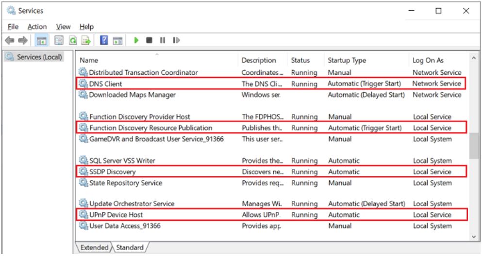
Open the Windows services by entering "Services" in the Windows search.
TipSelect an entry in the list of services offered and enter a "D", for example. This will take you to the services that begin with the letter "D", allowing you to navigate effectively through the list.
If necessary, start the following services and set the start type to Automatic:
DNS Client
Function Discovery Resource Publication
SSDP Discovery
UPnP Device Host
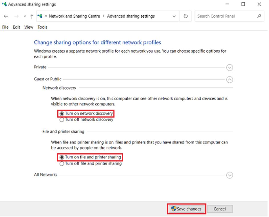
Also enable "Network discovery" and "File and printer sharing" in the Control Panel. These are available here:
Control Panel > All Control Panel Items > Network and Sharing Center > Change advanced sharing settings
Others
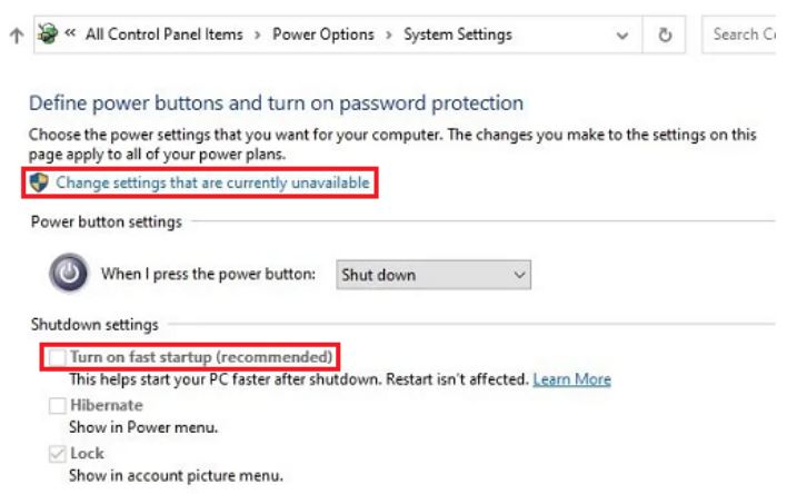
• Deactivate Power Saving Options of the network cards.
• Disable fast startup.
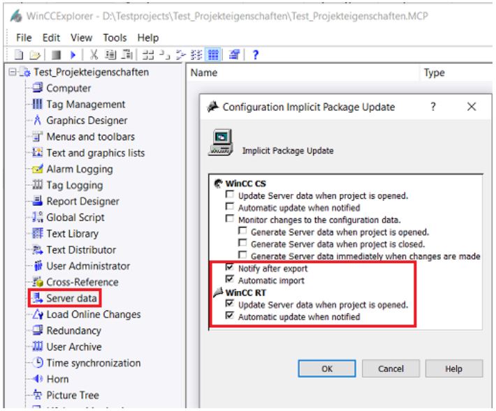
• Server Data. You must create the server package on the server with an implicit update.
Ethanol Project
Unregistered user. Buy the training at jats.com.br.