HW Config
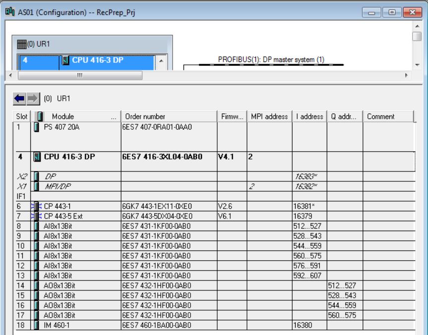
HW Config is where the hardware configuration of the SIMATIC Station (AS) is made.
To open HW Config, double-click on AS > Hardware.

AS_RecPrep
Rack 0 UR1 Principal
Slots
1 – PS 407 20A
4 – CPU 416-3 416-XL04-0AB0 V4.1.0
X2 – DP
6 – CP 443-1 443-1EX11-0XE0 V2.6
X1 – 192.168.0.1
7 – CP 443-5 Ext 443-5DX04-0XE0 V6.6
8 – AI 8x13Bit 431 1KF00-0AB0
9 – AI 8x13Bit 431 1KF00-0AB0
10 – AI 8x13Bit 431 1KF00-0AB0
11 – AI 8x13Bit 431 1KF00-0AB0
12 – AI 8x13Bit 431 1KF00-0AB0
13 – AI 8x13Bit 431 1KF00-0AB0
14 – AO 8x13Bit 432 1HFOC-0AB0
15 – AO 8x13Bit 432 1HFOC-0AB0
16 – AO 8x13Bit 432 1HFOC-0AB0
17 – AO 8x13Bit 432 1HFOC-0AB0
18 - IM460-1 460-1BA01-0AB0
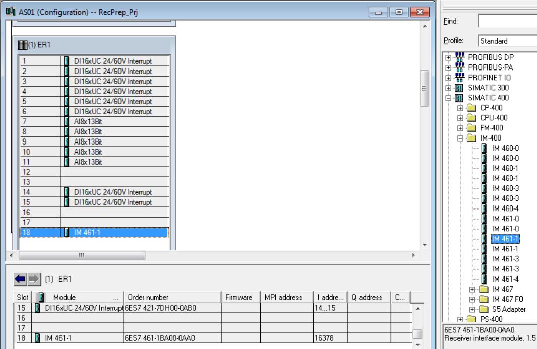
Rack 1 ER1 Extension
Slots
1 – DI16x24..60V 421-7DH00-0ABO
2 – DI16x24..60V 421-7DH00-0ABO
3 – DI16x24..60V 421-7DH00-0ABO
4 – DI16x24..60V 421-7DH00-0ABO
5 – DI16x24..60V 421-7DH00-0ABO
6 – DI16x24..60V 421-7DH00-0ABO
7 – AI 8x13Bit 431 1KF00-0AB0
8 – AI 8x13Bit 431 1KF00-0AB0
9 – AI 8x13Bit 431 1KF00-0AB0
10 – AI 8x13Bit 431 1KF00-0AB0
11 – AI 8x13Bit 431 1KF00-0AB0
12 – Empty
13 – Empty
14 – DI16x24..60V 421-7DH00-0ABO
15 – DI16x24..60V 421-7DH00-0ABO
16 – Empty
17 – Empty
18 - IM461-1 461-1BA01-0AA0
Rack 2 ER2 Extension
Slots
1 – DI16x24..60V 421-7DH00-0ABO
2 – DI16x24..60V 421-7DH00-0ABO
3 – DI16x24..60V 421-7DH00-0ABO
4 – DI16x24..60V 421-7DH00-0ABO
5 – DI16x24..60V 421-7DH00-0ABO
6 – DI16x24..60V 421-7DH00-0ABO
7 – DI16x24..60V 421-7DH00-0ABO
8 – DO16xUC24 422-1BDH00-0AAO
9 – DO16xUC24 422-1BDH00-0AAO
10 – DO16xUC24 422-1BDH00-0AAO
11 – DO16xUC24 422-1BDH00-0AAO
12 – DI16x24..60V 421-7DH00-0ABO
13 – AI 8x13Bit 431 1KF00-0AB0
14 – DI16x24..60V 421-7DH00-0ABO
15 – AI 8x13Bit 431 1KF00-0AB0
16 – Empty
17 – Empty
18 - IM461-1 461-1BA01-0AA0
• In the catalog, choose UR1 18 slots 6ES7 400-1TA00-0AA0 rack (Profile Standard > SIMATIC 400\RACK-400) and insert into the hardware (double-click on the item in the catalog).
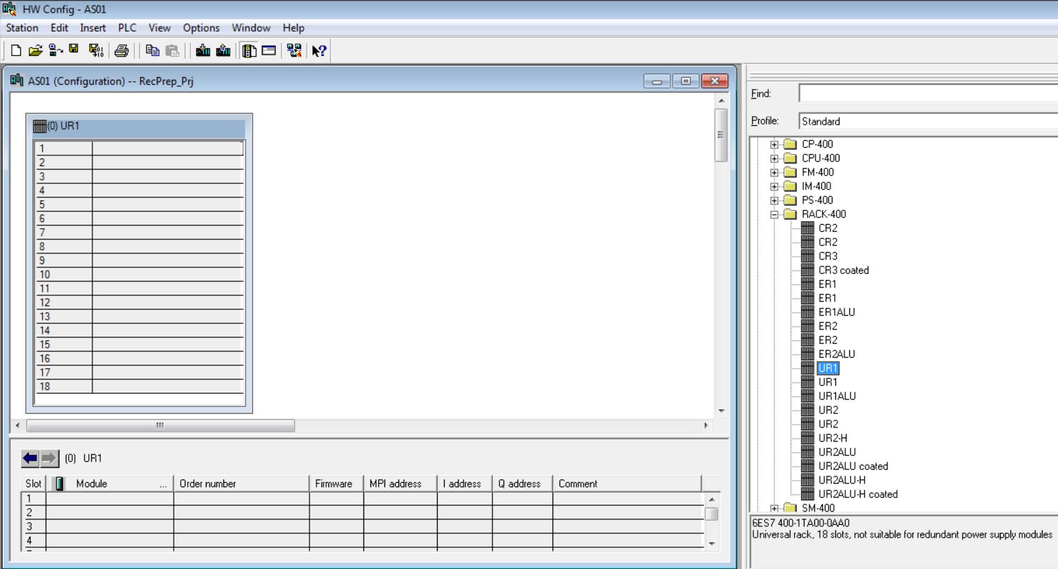
• Insert PS 407 20A 6ES7 407-0RA01-0AA0 power supply in rack 0 slot 1 (catalog - Profile Standard > SIMATIC 400\PS-400\Standard PS-400). Click with the mouse on the position in the rack to insert source (rack 0 slot1). Then double-click on the catalog item to be inserted.

• Insert CPU 416-3 6ES7 416-3XL04-0AB0 in rack 0 slot 4 (catalog - Profile Standard > SIMATIC 400\CPU-400\CPU 400\CPU 416-3 DP\6ES7 416-3XL04-0AB0). Click with the mouse on the position in the rack to insert (rack 0 slot 4). Then double-click on the catalog item to be inserted (V4.1).

• Create PROFIBUS(1) subnet. Click on New button.

On the Network Settings tab, configure the Profibus network with Transmission Rate 1.5 Mbps and Profile DP. The Profibus address of the CPU on the network is 2.
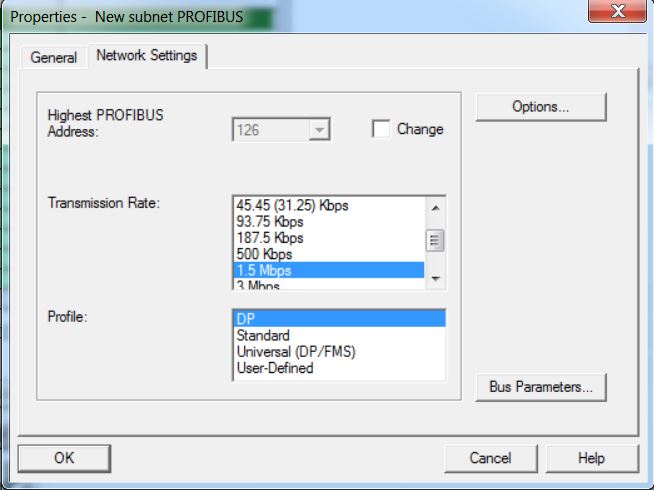
Click on OK.
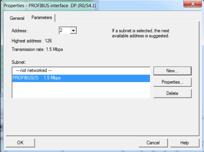
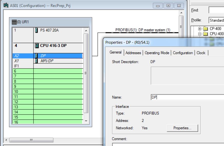
• Insert CP 443-1 6GK7 443-1EX11-0XE0 in rack 0 slot 6 (catalog - Profile Standard > SIMATIC 400\CP-400\Industrial Ethernet\CP 443-1\6GK7 443-1EX11-0XE0). Click with the mouse on the position in the rack to insert (rack 0 slot6). Then double-click on the catalog item to be inserted (V2.6).
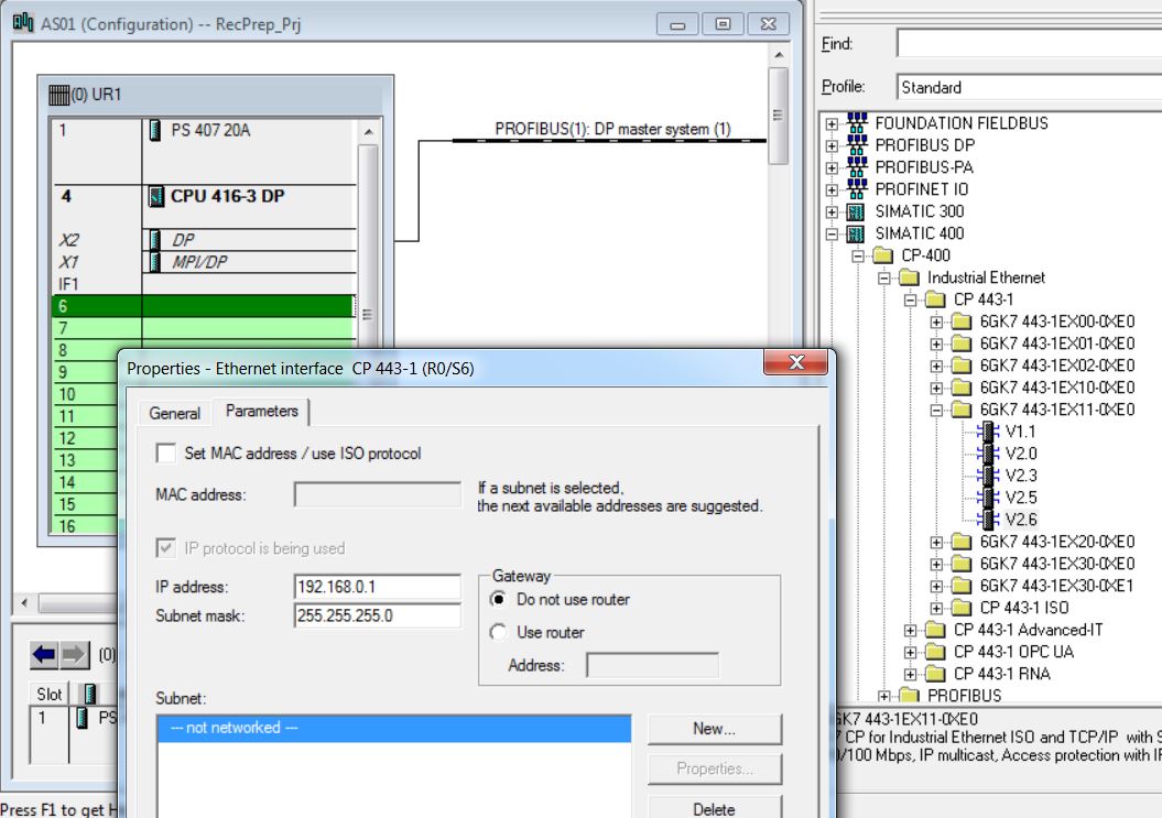
• Choose IP Address of the Ethernet interface R0/S6 of the CP443-1 - IP 192.168.0.1 and Mask 255.255.255.0.
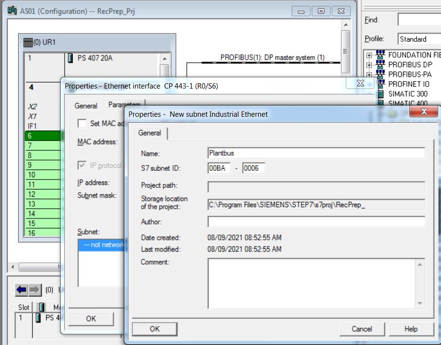
• Create Plantbus subnet.
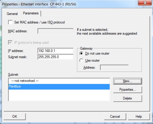
• Choose Plantbus subnet for CP 443-1.
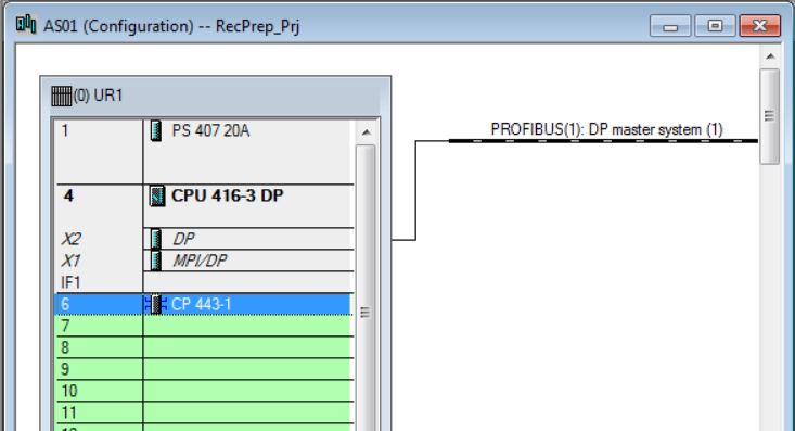
• Insert CP 443-5 Ext 6GK7 443-5DX04-0XE0 in rack 0 slot 7 (catalog - Profile Standard > SIMATIC 400\CP-400\PROFIBUS\CP 443-5 Extended\6GK7 443-5DX04-0XE0). Click with the mouse on the position in the rack to insert (rack 0 slot7). Then double-click on the catalog item to be inserted.
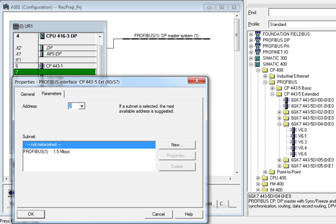
• Create Profibus_RecPrep subnet. Click on New button.
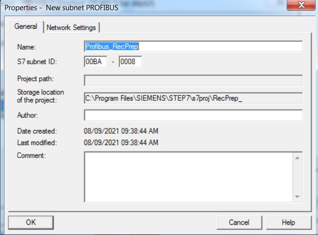
• On the Network Settings tab, configure the Profibus network with Transmission Rate 1.5 Mbps and Profile DP. The Profibus address of the CPU on the network is 2.
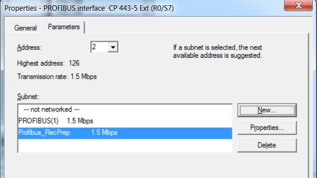
• Click on OK.
• In HW Config, open CPU416-3 properties. Right-click on the CPU and select Object Properties menu item.
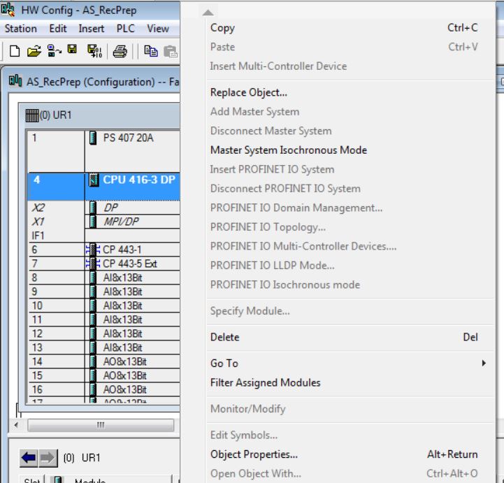
• Select Cyclic Interrupts tab and define OB32 with PIP2 Process Image Partition PIP2 and OB33 with PIP3 Process Image Partition.

• Insert AI-400 6ES7 431-1KF00-0AB0 analog input module in rack 0 slot 8 (catalog - Profile Standard > SIMATIC 400\SM-400\AI-400\AI8x13Bit). Click with the mouse on the position in the rack (rack 0 slot8). Then double-click on the catalog item to be inserted.
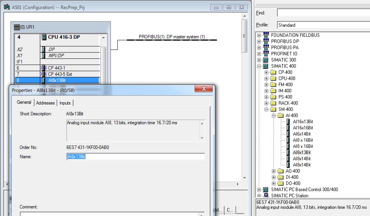
• Set Inputs: Start = 512; End=527; Process Image = PIP2. There are 2 bytes (1 word) for each analog input.

• Set all 8 analog inputs to 4DMU current (4-wire transmitter), Measuring Range = 4..20 mA and Interference Frequency = 60 Hz.
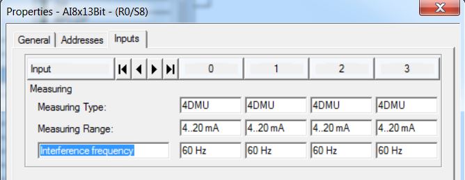
Note: PIP Process Image Partition will be handled with Organization Block (OB).
• Insert AI-400 6ES7 431-1KF00-0AB0 analog input module in rack 0 slot 9 (catalog - Profile Standard > SIMATIC 400\SM-400\AI-400\AI8x13Bit). Enter Inputs: Start = 528; End = 543; Process Image = PIP2. Set all 8 analog inputs to 4DMU current (4-wire transmitter), Measuring Range = 4..20 mA and Interference Frequency = 60 Hz.
• Insert AI-400 6ES7 431-1KF00-0AB0 analog input module in rack 0 slot 10 (catalog - Profile Standard > SIMATIC 400\SM-400\AI-400\AI8x13Bit). Enter Inputs: Start = 544; End = 559; Process Image = PIP2. Set all 8 analog inputs to 4DMU current (4-wire transmitter), Measuring Range = 4..20 mA and Interference Frequency = 60 Hz.
• Insert AI-400 6ES7 431-1KF00-0AB0 analog input module in rack 0 slot 11 (catalog - Profile Standard > SIMATIC 400\SM-400\AI-400\AI8x13Bit). Enter Inputs: Start = 560; End = 575; Process Image = PIP2. Set all 8 analog inputs to 4DMU current (4-wire transmitter), Measuring Range = 4..20 mA and Interference Frequency = 60 Hz.
• Insert AI-400 6ES7 431-1KF00-0AB0 analog input module in rack 0 slot 12 (catalog - Profile Standard > SIMATIC 400\SM-400\AI-400\AI8x13Bit). Enter Inputs: Start = 576; End = 591; Process Image = PIP2. Set all 8 analog inputs to 4DMU current (4-wire transmitter), Measuring Range = 4..20 mA and Interference Frequency = 60 Hz.
• Insert AI-400 6ES7 431-1KF00-0AB0 analog input in rack 0 slot 13 (catalog - Profile Standard > SIMATIC 400\SM-400\AI-400\AI8x13Bit). Enter Inputs: Start = 592; End = 607; Process Image = PIP2. Set all 8 analog inputs to 4DMU current (4-wire transmitter), Measuring Range = 4..20 mA and Interference Frequency = 60 Hz.
• Insert AO-400 6ES7 432-1HF00-0AB0 analog output module in rack 0 slot 14 (catalog - Profile Standard > SIMATIC 400\SM-400\AO-400\AO8x13Bit).

• Enter Outputs: Start = 512; End = 527; Process Image = PIP2. There are 2 bytes (1 word) for each analog output.
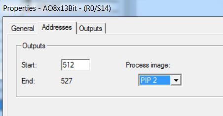
• Set all 8 analog outputs to I current and Output Range = 4..20 mA.
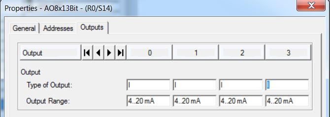
• Insert AO-400 6ES7 432-1HF00-0AB0 analog output module in rack 0 slot 15 (catalog - Profile Standard > SIMATIC 400\SM-400\AO-400\AO8x13Bit). Enter Outputs: Start = 528; End = 543; Process Image = PIP2. There are 2 bytes (1 word) for each analog output. Set all 8 analog outputs to I current and Output Range = 4..20 mA.
• Insert AO-400 6ES7 432-1HF00-0AB0 analog output module in rack 0 slot 16 (catalog - Profile Standard > SIMATIC 400\SM-400\AO-400\AO8x13Bit). Enter Outputs: Start = 544; End = 559; Process Image = PIP2. Set all 8 analog outputs to I current and Output Range = 4..20 mA.
• Insert AO-400 6ES7 432-1HF00-0AB0 analog output module in rack 0 slot 17 (catalog - Profile Standard > SIMATIC 400\SM-400\AO-400\AO8x13Bit). Enter Outputs: Start = 560; End = 575; Process Image = PIP2. Set all 8 analog outputs to I current and Output Range = 4..20 mA.
• Insert IM 460-1 6ES7 460-1BA01-0AB0 in rack 0 slot 18 (catalog - Profile Standard > SIMATIC 400\IM-400\IM 460-1\6ES7 460-1BA01-0AB0). Click with the mouse on the position in the rack to insert (rack 0 slot18). Then double-click on the catalog item to be inserted.

• In the catalog, choose ER1 18 slots 6ES7 403-1TA00-0AA0 rack (Profile Standard > SIMATIC 400\RACK-400) and insert into the hardware (double-click on the item in the catalog).

• Insert DI-400 6ES7 421-7DHF00-0AB0 digital input module in rack 1 slot 1 (catalog - Profile Standard > SIMATIC 400\SM-400\DI-400\DI16xUI24/60V interrupt). Click with the mouse on the position in the rack to insert (rack 1 slot1). Then double-click on the catalog item to be inserted.
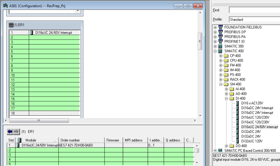
• Enter Inputs: Start = 0; End = 1; Process Image = PIP3. There are 2 bytes (1 bit for each digital input).
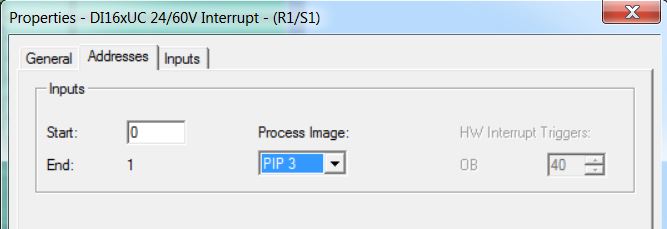
• Insert DI-400 6ES7 421-7DHF00-0AB0 digital input module in rack 1 slot 2 (catalog - Profile Standard > SIMATIC 400\SM-400\DI-400\DI16xUI24/60V interrupt). Enter Inputs: Start = 2; End = 3; Process Image = PIP3.
• Insert DI-400 6ES7 421-7DHF00-0AB0 digital input module in rack 1 slot 3 (catalog - Profile Standard > SIMATIC 400\SM-400\DI-400\DI16xUI24/60V interrupt). Enter Inputs: Start = 4; End = 5; Process Image = PIP3.
• Insert DI-400 6ES7 421-7DHF00-0AB0 digital input module in rack 1 slot 4 (catalog - Profile Standard > SIMATIC 400\SM-400\DI-400\DI16xUI24/60V interrupt). Enter Inputs: Start = 6; End = 7; Process Image = PIP3.
• Insert DI-400 6ES7 421-7DHF00-0AB0 digital input module in rack 1 slot 5 (catalog - Profile Standard > SIMATIC 400\SM-400\DI-400\DI16xUI24/60V interrupt). Enter Inputs: Start = 8; End = 9; Process Image = PIP3.
• Insert DI-400 6ES7 421-7DHF00-0AB0 digital input module in rack 1 slot 6 (catalog - Profile Standard > SIMATIC 400\SM-400\DI-400\DI16xUI24/60V interrupt). Enter Inputs: Start = 10; End = 11; Process Image = PIP3.
• Insert AI-400 6ES7 431-1KF00-0AB0 analog input module in rack 1 slot 7 (catalog - Profile Standard > SIMATIC 400\SM-400\AI-400\AI8x13Bit). Enter Inputs: Start = 608; End = 623; Process Image = PIP2. Set all 8 analog inputs to 4DMU current (4-wire transmitter), Measuring Range = 4..20 mA and Interference Frequency = 60 Hz.
• Insert AI-400 6ES7 431-1KF00-0AB0 analog input module in rack 1 slot 8 (catalog - Profile Standard > SIMATIC 400\SM-400\AI-400\AI8x13Bit). Enter Inputs: Start = 624; End = 639; Process Image = PIP2. Set all 8 analog inputs to 4DMU current (4-wire transmitter), Measuring Range = 4..20 mA and Interference Frequency = 60 Hz.
• Insert AI-400 6ES7 431-1KF00-0AB0 analog input module in rack 1 slot 9 (catalog - Profile Standard > SIMATIC 400\SM-400\AI-400\AI8x13Bit). Enter Inputs: Start = 640; End = 655; Process Image = PIP2. Set all 8 analog inputs to 4DMU current (4-wire transmitter), Measuring Range = 4..20 mA and Interference Frequency = 60 Hz.
• Insert AI-400 6ES7 431-1KF00-0AB0 analog input module in rack 1 slot 10 (catalog - Profile Standard > SIMATIC 400\SM-400\AI-400\AI8x13Bit). Enter Inputs: Start = 656; End = 671; Process Image = PIP2. Set all 8 analog inputs to 4DMU current (4-wire transmitter), Measuring Range = 4..20 mA and Interference Frequency = 60 Hz.
• Insert AI-400 6ES7 431-1KF00-0AB0 analog input module in rack 1 slot 11 (catalog - Profile Standard > SIMATIC 400\SM-400\AI-400\AI8x13Bit). Enter Inputs: Start = 672; End = 687; Process Image = PIP2. Set all 8 analog inputs to 4DMU current (4-wire transmitter), Measuring Range = 4..20 mA and Interference Frequency = 60 Hz.
• Insert DI-400 6ES7 421-7DHF00-0AB0 digital input module in rack 1 slot 14 (catalog - Profile Standard > SIMATIC 400\SM-400\DI-400\DI16xUI24/60V interrupt). Enter Inputs: Start = 12; End = 13; Process Image = PIP3.
• Insert DI-400 6ES7 421-7DHF00-0AB0 digital input module in rack 1 slot 15 (catalog - Profile Standard > SIMATIC 400\SM-400\DI-400\DI16xUI24/60V interrupt). Enter Inputs: Start = 14; End = 15; Process Image = PIP3.
• Insert IM 461-1 6ES7 461-1BA01-0AA0 in rack 1 slot 18 (catalog - Profile Standard > SIMATIC 400\IM-400\IM 461-1\6ES7 461-1BA01-0AA0). Click with the mouse on the position in the rack to insert (rack 1 slot18). Then double-click on the catalog item to be inserted.

• In the catalog, choose ER1 18 slots 6ES7 403-1TA00-0AA0 rack (Profile Standard > SIMATIC 400\RACK-400) and insert into the hardware (double-click on the item in the catalog).

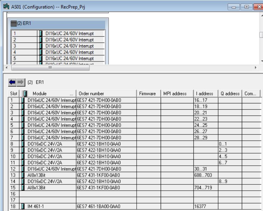
• Insert DI-400 6ES7 421-7DHF00-0AB0 digital input module in rack 2 slot 1 (catalog - Profile Standard > SIMATIC 400\SM-400\DI-400\DI16xUI24/60V interrupt). Enter Inputs: Start = 16; End = 17; Process Image = PIP3.
• Insert DI-400 6ES7 421-7DHF00-0AB0 digital input module in rack 2 slot 2 (catalog - Profile Standard > SIMATIC 400\SM-400\DI-400\DI16xUI24/60V interrupt). Enter Inputs: Start = 18; End = 19; Process Image = PIP3.
• Insert DI-400 6ES7 421-7DHF00-0AB0 digital input module in rack 2 slot 3 (catalog - Profile Standard > SIMATIC 400\SM-400\DI-400\DI16xUI24/60V interrupt). Enter Inputs: Start = 20; End = 21; Process Image = PIP3.
• Insert DI-400 6ES7 421-7DHF00-0AB0 digital input module in rack 2 slot 4 (catalog - Profile Standard > SIMATIC 400\SM-400\DI-400\DI16xUI24/60V interrupt). Enter Inputs: Start = 22; End = 23; Process Image = PIP3.
• Insert DI-400 6ES7 421-7DHF00-0AB0 digital input module in rack 2 slot 5 (catalog - Profile Standard > SIMATIC 400\SM-400\DI-400\DI16xUI24/60V interrupt). Enter Inputs: Start = 24; End = 25; Process Image = PIP3.
• Insert DI-400 6ES7 421-7DHF00-0AB0 digital input module in rack 2 slot 6 (catalog - Profile Standard > SIMATIC 400\SM-400\DI-400\DI16xUI24/60V interrupt). Enter Inputs: Start = 26; End = 27; Process Image = PIP3.
• Insert DI-400 6ES7 421-7DHF00-0AB0 digital input module in rack 2 slot 7 (catalog - Profile Standard > SIMATIC 400\SM-400\DI-400\DI16xUI24/60V interrupt). Enter Inputs: Start = 28; End = 29; Process Image = PIP3.
• Insert DO-400 6ES7 422-1BH10-0AA0 digital output module in rack 2 slot 8 (catalog - Profile Standard > SIMATIC 400\SM-400\DO-400\DO16xDC 24/2A). Click with the mouse on the position in the rack to insert (rack 2 slot 8). Then double-click on the catalog item to be inserted. Enter Outputs: Start = 0; End = 1; Process Image = PIP3.
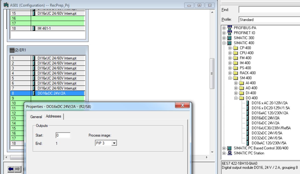
• Insert DO-400 6ES7 422-1BH10-0AA0 digital output module in rack 2 slot 9 (catalog - Profile Standard > SIMATIC 400\SM-400\DI-400\DO16xDC 24/2A). Enter Outputs: Start = 2; End = 3; Process Image = PIP3.
• Insert DO-400 6ES7 422-1BH10-0AA0 digital output module in rack 2 slot 10 (catalog - Profile Standard > SIMATIC 400\SM-400\DI-400\DO16xDC 24/2A). Enter Outputs: Start = 4; End = 5; Process Image = PIP3.
• Insert DO-400 6ES7 422-1BH10-0AA0 digital output module in rack 2 slot 11 (catalog - Profile Standard > SIMATIC 400\SM-400\DI-400\DO16xDC 24/2A). Enter Outputs: Start = 6; End = 7; Process Image = PIP3.
• Insert DI-400 6ES7 421-7DHF00-0AB0 digital input module in rack 2 slot 12 (catalog - Profile Standard > SIMATIC 400\SM-400\DI-400\DI16xUI24/60V interrupt). Enter Inputs: Start = 30; End = 31; Process Image = PIP3.
• Insert AI-400 6ES7 431-1KF00-0AB0 analog input module in rack 2 slot 13 (catalog - Profile Standard > SIMATIC 400\SM-400\AI-400\AI8x13Bit). Enter Inputs: Start = 688; End = 703; Process Image = PIP2. Set all 8 analog inputs to 4DMU current (4-wire transmitter), Measuring Range = 4..20 mA and Interference Frequency = 60 Hz.
• Insert DO-400 6ES7 422-1BH10-0AA0 digital output module in rack 2 slot 14 (catalog - Profile Standard > SIMATIC 400\SM-400\DI-400\DO16xDC 24/2A). Enter Outputs: Start = 8; End = 9; Process Image = PIP3.
• Insert AI-400 6ES7 431-1KF00-0AB0 analog input module in rack 2 slot 15 (catalog - Profile Standard > SIMATIC 400\SM-400\AI-400\AI8x13Bit). Enter Inputs: Start = 704; End = 719; Process Image = PIP2. Set all 8 analog inputs to 4DMU current (4-wire transmitter), Measuring Range = 4..20 mA and Interference Frequency = 60 Hz.
• Insert IM 461-1 6ES7 461-1BA01-0AA0 in rack 2 slot 18 (catalog - Profile Standard > SIMATIC 400\IM-400\IM 461-1\6ES7 461-1BA01-0AA0).
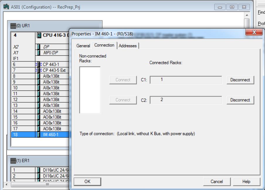
• Associate racks 1 and 2 with rack 0 (central rack). Open IM 460-1 module properties (rack 0 slot 18). Select rack 1 and click on the Connect button. Select rack 2 and click on the Connect button.
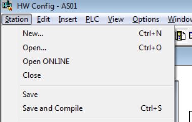
• Save and compile hardware (Station > Save and Compile menu item).
• Close HW Config (Station > Exit menu item).
Wiring the S7-400
Supplying Power to Modules
Power Supply Modules and Load Current Power Supplies
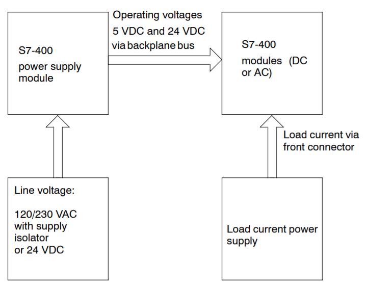
The modules of the S7-400 system are supplied with all the required operating voltages by a power supply module, via the backplane bus of the rack. Which power supply module you use in a rack depends on your system requirements (line voltage, current consumption of the modules used).
You must provide load voltages and currents via external load current power supplies.
The following figure shows how the individual modules of the S7-400 are supplied with current and voltage.
Interconnecting the CR and ER(s)
When you assemble an automation system comprising a CR and one or more ERs, you connect the racks via the connecting cables of the interface modules.
• Plug the male connector of the first connecting cable into one of the female connectors of the send IM and screw-tighten it.
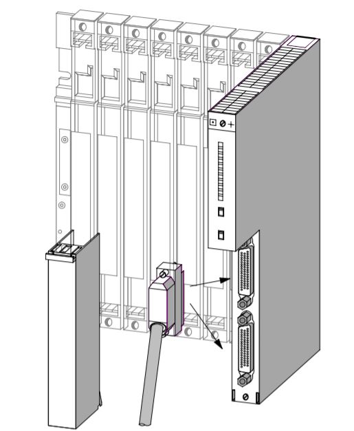
• Plug the free end of the connecting cable into the upper male connector (receive interface) of the receive IM and screw the connector on.
• Connect the remaining receive IMs by connecting one send interface (lower female connector X2) to one receive interface (upper male connector X1) in each case.

• Plug the terminator into the lower female connector of the receive IM in the last ER of the chain.
Crushing Soy Project
Equipments
Motors
| Tag | Description | Type |
|---|---|---|
| TCR0802A | TCR0802A Redler Motor | Direct Start |
| EL0803A | EL0803A Elevator Motor | Soft Start |
| EL0805A | EL0805A Elevator Motor | Soft Start |
| TCR0809 | TCR0809 Redler Motor | Soft Start |
| TCR0806 | TCR0806 Redler Motor | Soft Start |
| VT0807A_1 | SP-0807A Silo Fan 1 | Soft Start |
| RO0807A | SP0807A Silo Sweeper Thread Motor | Direct Start |
| CT0808 | CT0808 Redler Motor | Direct Start |
| VT0811A_1 | SEC0811A Dryer Fan | Direct Start |
| TCR0813 | TCR0813 Redler Motor | Soft Start |
| CT0812A | CT0812A Conveyor Belt Motor | Direct Start |
| EL1001A | EL1001A Elevator Motor | Soft Start |
| CT2501 | CT2501 Conveyor Belt Motor | Direct Start |
| TP2502 | CT2502 Tripper | Direct Start |
| CT2502 | CT2502 Conveyor Belt Motor | Direct Start |
| VT2500_1 | Store 2501 Fan 1 | Soft Start |
| VT0804A_A | PL0804A Sieve Pre-separator Fan 1 | Soft Start |
| VT0804A_B | PL0804A Sieve Pre-separator Fan 2 | Soft Start |
| AL0804A | PL0804A Sieve Feeder Motor | Direct Start |
| PN0804A | PL-0804A Sieve Motor | Direct Start |
| RO0804A | PL0804A Sieven Discharge Thread Motor | Direct Start |
| RO0901 | RO0901 Thread Motor | Soft Start |
| RO0902 | RO0902 Thread Motor | Direct Start |
| RO0903 | RO0903 Thread Motor | Direct Start |
| VC0804A | CL0804A Cyclone Centrifugal Fan | Direct Start |
| VR0804A | CL0804A Cyclone Rotary Valve | Direct Start |
| VT0815 | FM0815 Bag Filter Fan | Direct Start |
| FL0815 | FM0815 Bag Filter Flute | Direct Start |
| VR0815 | FM0815 Bag Filter Rotary Valve | Direct Start |
| EX0815 | FM0815 Bag Filter Exhaust | Soft Start |
| VR1307A | Bean Heater Rotary Valve | Frequency Inverter |
Hardware I/O
| Address | Symbol | Data type | Comment |
|---|---|---|---|
| IW512 | TCR0802A_II | WORD | TCR0802A Redler Motor Current |
| IW514 | EL0803A_II | WORD | EL0803A Elevator Motor Current |
| IW516 | EL0805A_II | WORD | EL0805A Elevator Motor Current |
| IW518 | TCR0809_II | WORD | TCR0809 Redler Motor Current |
| IW520 | TCR0806_II | WORD | TCR0806 Redler Motor Current |
| IW522 | VT0807A_1_II | WORD | SP-0807A Silo Fan 1 Current |
| IW524 | RO0807A_II | WORD | SP0807A Silo Sweeper Thread Motor Current |
| IW526 | CT0808_II | WORD | CT0808 Redler Motor Current |
| Address | Symbol | Data type | Comment |
|---|---|---|---|
| IW528 | VT0811A_1_II | WORD | SEC0811A Dryer Fan Current |
| IW530 | TCR0813_II | WORD | TCR0813 Redler Motor Current |
| IW532 | CT0812A_II | WORD | CT0812A Conveyor Belt Motor Current |
| IW534 | EL1001A_II | WORD | EL1001A Elevator Motor Current |
| IW536 | CT2501_II | WORD | CT2501 Conveyor Belt Motor Current |
| IW538 | TP2502_II | WORD | CT2502 Tripper Current |
| IW540 | CT2502_II | WORD | CT2502 Conveyor Belt Motor Current |
| IW542 | VT2500_1_II | WORD | Store 2501 Fan 1 Current |
| Address | Symbol | Data type | Comment |
|---|---|---|---|
| IW544 | VT0804A_A_II | WORD | PL0804A Sieve Pre-separator Fan 1 Current |
| IW546 | VT0804A_B_II | WORD | PL0804A Sieve Pre-separator Fan 2 Current |
| IW548 | AL0804A_II | WORD | PL0804A Sieve Feeder Motor Current |
| IW550 | PN0804A_II | WORD | PL-0804A Sieve Motor Current |
| IW552 | RO0804A_II | WORD | PL0804A Sieven Discharge Thread Motor Current |
| IW554 | RO0901_II | WORD | RO0901 Thread Motor Current |
| IW556 | RO0902_II | WORD | RO0902 Thread Motor Current |
| IW558 | RO0903_II | WORD | RO0903 Thread Motor Current |
| Address | Symbol | Data type | Comment |
|---|---|---|---|
| IW560 | VC0804A_II | WORD | CL0804A Cyclone Centrifugal Fan Current |
| IW562 | VR0804A_II | WORD | CL0804A Cyclone Rotary Valve Current |
| IW564 | VT0815_II | WORD | FM0815 Bag Filter Fan Current |
| IW566 | FL0815_II | WORD | FM0815 Bag Filter Flute Current |
| IW568 | VR0815_II | WORD | FM0815 Bag Filter Rotary Valve Current |
| IW570 | EX0815_II | WORD | FM0815 Bag Filter Exhaust Current |
| IW572 | VR1307A_II | WORD | VR1307A Bean Heater Rotary Valve Current |
| IW574 | LT1307 | WORD | Bean Heater Level |
| Address | Symbol | Data type | Comment |
|---|---|---|---|
| QW512 | VR1307A_SR | WORD | VR1307A Bean Heater Rotary Valve Speed Reference |
| Address | Symbol | Data type | Comment |
|---|---|---|---|
| I0.0 | TCR0802A_YS | BOOL | TCR0802A Redler Motor Status |
| I0.1 | EL0803A_YS | BOOL | EL0803A Elevator Motor Status |
| I0.2 | EL0803A_CF | BOOL | EL0803A Elevator Motor Fault |
| I0.3 | EL0805A_YS | BOOL | EL0805A Elevator Motor Status |
| I0.4 | EL0805A_CF | BOOL | EL0805A Elevator Motor Fault |
| I0.5 | TCR0809_YS | BOOL | TCR0809 Redler Motor Status |
| I0.6 | TCR0809_CF | BOOL | TCR0809 Redler Motor Fault |
| I0.7 | TCR0806_YS | BOOL | TCR0806 Redler Motor Status |
| I1.0 | TCR0806_CF | BOOL | TCR0806 Redler Motor Fault |
| I1.1 | VT0807A_1_YS | BOOL | SP-0807A Silo Fan 1 Status |
| I1.2 | VT0807A_1_CF | BOOL | SP-0807A Silo Fan 1 Fault |
| I1.3 | RO0807A_YS | BOOL | SP0807A Silo Sweeper Thread Motor Status |
| I1.4 | CT0808_YS | BOOL | CT0808 Redler Motor Status |
| I1.5 | VT0811A_1_YS | BOOL | SEC0811A Dryer Fan Status |
| I1.6 | TCR0813_YS | BOOL | TCR0813 Redler Motor Status |
| I1.7 | TCR0813_CF | BOOL | TCR0813 Redler Motor Fault |
| Address | Symbol | Data type | Comment |
|---|---|---|---|
| I2.0 | CT0812A_YS | BOOL | CT0812A Conveyor Belt Motor Status |
| I2.1 | EL1001A_YS | BOOL | EL1001A Elevator Motor Status |
| I2.2 | EL1001A_CF | BOOL | EL1001A Elevator Motor Fault |
| I2.3 | CT2501_YS | BOOL | CT2501 Conveyor Belt Motor Status |
| I2.4 | CT2501_CF | BOOL | CT2501 Conveyor Belt Motor Fault |
| I2.5 | TP2502_YS | BOOL | CT2502 Tripper Status |
| I2.6 | CT2502_YS | BOOL | CT2502 Conveyor Belt Motor Status |
| I2.7 | VT2500_1_YS | BOOL | Store 2501 Fan 1 Status |
| I3.0 | VT2500_1_CF | BOOL | Store 2501 Fan 1 Fault |
| I3.1 | VT0804A_A_YS | BOOL | PL0804A Sieve Pre-separator Fan 1 Status |
| I3.2 | VT0804A_A_CF | BOOL | PL0804A Sieve Pre-separator Fan 1 Fault |
| I3.3 | VT0804A_B_YS | BOOL | PL0804B Sieve Pre-separator Fan 2 Status |
| I3.4 | VT0804A_B_CF | BOOL | PL0804B Sieve Pre-separator Fan 2 Fault |
| I3.5 | AL0804A_YS | BOOL | PL0804A Sieve Feeder Motor Status |
| I3.6 | PN0804A_YS | BOOL | PL-0804A Sieve Motor Status |
| I3.7 | RO0804A_YS | BOOL | PL0804A Sieven Discharge Thread Motor Status |
| Address | Symbol | Data type | Comment |
|---|---|---|---|
| I4.0 | RO0901_YS | BOOL | RO0901 Thread Motor Status |
| I4.1 | RO0901_CF | BOOL | RO0901 Thread Motor Fault |
| I4.2 | RO0902_YS | BOOL | RO0902 Thread Motor Status |
| I4.3 | RO0903_YS | BOOL | RO0903 Thread Motor Status |
| I4.4 | VC0804A_YS | BOOL | CL0804A Cyclone Centrifugal Fan Status |
| I4.5 | VR0804A_YS | BOOL | CL0804A Cyclone Rotary Valve Status |
| I4.6 | VT0815_YS | BOOL | FM0815 Bag Filter Fan Status |
| I4.7 | FL0815_YS | BOOL | FM0815 Bag Filter Flute Status |
| I5.0 | VR0815_YS | BOOL | FM0815 Bag Filter Rotary Valve Status |
| I5.1 | EX0815_YS | BOOL | FM0815 Bag Filter Exhaust Status |
| I5.2 | EX0815_CF | BOOL | FM0815 Bag Filter Exhaust Fault |
| I5.3 | MOS0803A | BOOL | EL0803A Motion Sensor |
| I5.4 | MAS0803A_1 | BOOL | EL0803A Misalignment Sensor 1 |
| I5.5 | MAS0803A_2 | BOOL | EL0803A Misalignment Sensor 2 |
| I5.6 | V0804A_ZSC | BOOL | V0804A Valve Closed Status |
| I5.7 | V0804A_ZSO | BOOL | V0804A Valve Opened Status |
| Address | Symbol | Data type | Comment |
|---|---|---|---|
| I6.0 | VR1307A_YS | BOOL | VR1307A Bean Heater Rotary Valve Status |
| I6.1 | VR1307A_CF | BOOL | VR1307A Bean Heater Rotary Valve Fault |
| Address | Symbol | Data type | Comment |
|---|---|---|---|
| Q0.0 | TCR0802A_YC | BOOL | TCR0802A Redler Motor Command |
| Q0.1 | EL0803A_YC | BOOL | EL0803A Elevator Motor Command |
| Q0.2 | EL0805A_YC | BOOL | EL0805A Elevator Motor Command |
| Q0.3 | TCR0809_YC | BOOL | TCR0809 Redler Motor Command |
| Q0.4 | TCR0806_YC | BOOL | TCR0806 Redler Motor Command |
| Q0.5 | VT0807A_1_YC | BOOL | SP-0807A Silo Fan 1 Command |
| Q0.6 | RO0807A_YC | BOOL | SP0807A Silo Sweeper Thread Motor Command |
| Q0.7 | CT0808_YC | BOOL | CT0808 Redler Motor Command |
| Q1.0 | VT0811A_1_YC | BOOL | SEC0811A Dryer Fan Command |
| Q1.1 | TCR0813_YC | BOOL | TCR0813 Redler Motor Command |
| Q1.2 | CT0812A_YC | BOOL | CT0812A Conveyor Belt Motor Command |
| Q1.3 | EL1001A_YC | BOOL | EL1001A Elevator Motor Command |
| Q1.4 | CT2501_YC | BOOL | CT2501 Conveyor Belt Motor Command |
| Q1.5 | TP2502_YC | BOOL | CT2502 Tripper Command |
| Q1.6 | CT2502_YC | BOOL | CT2502 Conveyor Belt Motor Command |
| Q1.7 | VT2500_1_YC | BOOL | Store 2501 Fan 1 Command |
| Address | Symbol | Data type | Comment |
|---|---|---|---|
| Q2.0 | VT0804A_A_YC | BOOL | PL0804A Sieve Pre-separator Fan 1 Command |
| Q2.1 | VT0804A_B_YC | BOOL | PL0804B Sieve Pre-separator Fan 2 Command |
| Q2.2 | AL0804A_YC | BOOL | PL0804A Sieve Feeder Motor Command |
| Q2.3 | PN0804A_YC | BOOL | PL-0804A Sieve Motor Command |
| Q2.4 | RO0804A_YC | BOOL | PL0804A Sieven Discharge Thread Motor Command |
| Q2.5 | RO0901_YC | BOOL | RO0901 Thread Motor Command |
| Q2.6 | RO0902_YC | BOOL | RO0902 Thread Motor Command |
| Q2.7 | RO0903_YC | BOOL | RO0903 Thread Motor Command |
| Q3.0 | VC0804A_YC | BOOL | CL0804A Cyclone Centrifugal Fan Command |
| Q3.1 | VR0804A_YC | BOOL | CL0804A Cyclone Rotary Valve Command |
| Q3.2 | VT0815_YC | BOOL | FM0815 Bag Filter Fan Command |
| Q3.3 | FL0815_YC | BOOL | FM0815 Bag Filter Flute Command |
| Q3.4 | VR0815_YC | BOOL | FM0815 Bag Filter Rotary Valve Command |
| Q3.5 | EX0815_YC | BOOL | FM0815 Bag Filter Exhaust Command |
| Q3.6 | V0804A_XV | BOOL | V0804A Valve Command |
| Q3.7 | VR1307A_YC | BOOL | VR1307A Bean Heater Rotary Valve Command |
• Edit symbols - enter description of all I/O channels.

You can enter all the symbols in the Crushing Soy project one by one or import the symbols at once. Below the Symbols Table is the option to import symbols. Request the import file (ASCII format).
Click here to download the file with the symbols tableSymbols Table
All symbols of an AS can be seen in Symbols (Factory_Prj > AS01 > CPU 416-3 DP > S7 Program(1) > Symbols).


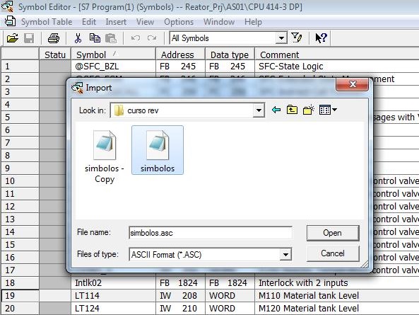
The Symbols table can be exported (Symbol Table menu > Export ...) and new symbols can be imported (Symbol Table menu > Import...). The image below shows the file import in ASCII format with new symbols.
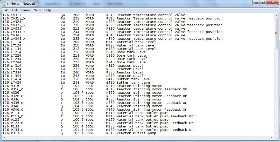
ASCII file with I/O symbols from the Crushing Soy project.
S7-400
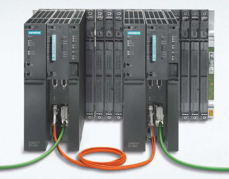
The S7-400 is the most powerful PLC in the SIMATIC controller family.
The S7-400 is an automation platform for system solutions in production and process engineering, and is primarily characterized by its modularity and performance reserves.
S7-400
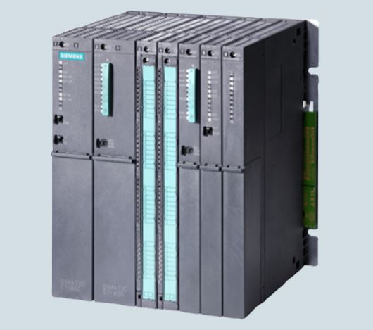
• Power PLC for medium to high end performance ranges.
• Solution for the most demanding tasks.
• With a comprehensive range of modules and CPUs with adequate performance for optimal adaptation to the automation task.
• Flexible in use through simple implementation of distributed structures.
• Friendly connections.
• Great communication and networking options.
• Easy-to-use handling and simple design.
• It can be expanded without problems when tasks increase.
• Multicomputing: simultaneous operation of multiple CPUs on an S7-400 central controller. Multicomputing distributes the overall performance power of an S7-400. For example, complex tasks can be broken down into technologies such as open-loop control, computing or communication, and assigned to different CPUs. And every CPU can receive its own local I/O.
• Modularity: The S7-400's powerful backplane bus and communication interfaces that can be directly connected to the CPU enable high-performance operation of a series of communication lines. This allows, for example, to split into a communication path for HMI and programming tasks, one for equidistant and high-performance motion control components and one for a "normal" I/O fieldbus. In addition, the necessary connections to MES/ERP systems or to the Internet can also be implemented.
• Engineering and diagnostics: The S7-400 is configured and programmed extremely efficiently in conjunction with SIMATIC engineering tools, especially in the case of extensive automation solutions with a high engineering component. For this purpose, for example, high-level languages such as SCL and graphical engineering tools for sequential controls, state graphics programs and technology-oriented diagrams are available.
S7-400 Installation
An S7-400 programmable controller consists of a central rack (CR) and one or more expansion racks (ERs), as required. You can add ERs to compensate for lack of slots for your application or operate signal modules at remote locations (e.g. in the immediate vicinity of your process).
When using ERs, you need interface modules (IMs) as well as the additional racks, and additional power supply modules if necessary. When using interface modules, you must always use the appropriate partners: you insert a send IM in the CR, and the matching receive IM in each connected ER.
Central Rack (CR) and Expansion Rack (ER)
The rack containing the CPU is known as the central rack (CR). The racks containing modules in the system and connected to the CR are the expansion racks (ERs).

Connecting the CR and ER(s)
To connect one or more ERs to a CR, you must fit one or more send IMs in the CR. The send IMs have two interfaces. You can connect one chain of up to four ERs to each of the two interfaces of a send IM in the CR. Different IMs are available for local connection and remote connection.
Connecting with a 5V Supply
For a local connection with the IM 460-1 and IM 461-1, the 5 V supply voltage is also transferred via the interface modules. There must therefore be no power supply module inserted in an ER connected to an IM 460-1/IM 461-1.
Up to 5 A may flow through each of the two interfaces of an IM 460-1. This means that each ER connected via an IM 460-1/461-1 can be powered with a maximum of 5 A at 5 V.
Observe the connection rules.
| Item | Local Connection | Remote Connection | ||
|---|---|---|---|---|
| Send IM | 460-0 | 460-1 | 460-3 | 460-4 |
| Receive IM | 461-0 | 461-1 | 461-3 | 461-4 |
| Max. number of connectable EMs per chain | 4 | 1 | 4 | 4 |
| Max. distance | 5 m | 1.5 m | 102.15 m | 605 m |
| 5 V transfer | No | Yes | No | No |
| Max. current transfer per interface | - | 5 A | - | - |
| Communication bus transmission | Yes | No | Yes | No |
Ways of Connecting Central and Expansion Racks

Installing the Central Rack (CR) and Expansion Rack (ER)
The racks of the S7-400 system form the basic framework which accepts the individual modules. The modules exchange data and signals and are powered via the backplane bus. The racks are designed for wall mounting, for mounting on rails, and for installation in frames and cabinets.
Racks in the S7-400 System
| Racks | Slots | Available Buses | Application | Characteristics |
|---|---|---|---|---|
| UR1 | 18 | I/O bus, Communication bus | CR ou ER | Rack for all module types in the S7 400 |
| UR2 | 9 | I/O bus, Communication bus | CR ou ER | Rack for all module types in the S7 400 |
| ER1 | 18 | Restricted I/O bus | ERs | Racks for signal modules (SMs), receive IMs, and all power supply modules. The I/O bus has the following restrictions: Interrupts from modules have no effect because no interrupt lines exist; Modules are not supplied with 24 V, ER2 9 Restricted I/O bus ERs Modules are not supplied with 24 V, i.e. modules requiring 24 V cannot be used; Modules are neither backed up by the battery in the power supply module nor by the voltage applied externally to the CPU or receive IM (EXT.BATT. socket). |
| ER2 | 9 | Restricted I/O bus | ERs | Racks for signal modules (SMs), receive IMs, and all power supply modules. The I/O bus has the following restrictions: Interrupts from modules have no effect because no interrupt lines exist; Modules are not supplied with 24 V, ER2 9 Restricted I/O bus ERs Modules are not supplied with 24 V, i.e. modules requiring 24 V cannot be used; Modules are neither backed up by the battery in the power supply module nor by the voltage applied externally to the CPU or receive IM (EXT.BATT. socket). |
| CR2 | 18 | I/O bus, segmented Communication bus, continuos | Segmented CR | Rack for all module types in the S7-400 except receive IMs. The I/O bus is subdivided into 2 I/O bus segments of 10 and 8 slots respectively. |
| CR3 | 4 | I/O bus, Communication bus | CR in stardard systems | Racks for all S7-400 module types except receive IMs. CPUs 41x-H only in stand-alone operation. |
| UR2-H | 2*9 | I/O bus, segmented Communication bus, segmenteds | Subdivided CR or ER for compact installation of a fault-tolerant system | Rack for all S7-400 modules except send IMs. The I/O bus and communication bus are divided into 2 bus segments, each with 9 slots. |
Electrical Supply
The modules inserted in the rack are supplied with the required operating voltages (5 V for logic, 24 V for interfaces) via the backplane bus and base connector, by the power supply module fitted in the slot on the extreme left in the rack.
For local connections, ERs can also be supplied with power via the IM 460-1/IM 461-1 interface modules.
5 A may flow through each of the two interfaces of a send IM 460-1, meaning each ER in a local connection can be supplied with up to 5 A.
I/O Bus
The I/O bus is a parallel backplane bus designed for the fast interchange of I/O signals. Each rack has an I/O bus. Time-critical operations to access the process data of the signal modules take place via the I/O bus.
Communication Bus (C Bus)
The communication bus (C bus) is a serial backplane bus designed for the fast exchange of large volumes of data parallel to the I/O signals. Except for racks ER1 and ER2, each rack has a communication bus.
Rack with I/O Bus and Communication Bus
The following figure shows a rack with an I/O bus and a communication bus. The I/O bus connector and communication bus connector can be seen at each slot. When the rack is delivered, these connectors are protected by a cover.

Segmented CR
The “segmented” characteristic relates to the configuration of the CR. In the (non-segmented) CR the I/O bus is continuous and interconnects all 18 or 9 slots; in the segmented CR, however, the I/O bus consists of two I/O bus segments.
A segmented CR has the following important characteristics:
• The communication bus is continuous (global), whilst the I/O bus is divided into two I/O bus segments of 10 and 8 slots respectively.
• One CPU can be inserted per local bus segment.
• The two CPUs in a segmented CR may be in different operating states.
• The two CPUs can communicate with each other via the communication bus.
• All the modules inserted in a segmented CR are powered by the power supply module at slot 1.
• Both segments have a common backup battery.
The following image shows a segmented CR with divided I/O bus and continuous communication bus.

Subdivided CR
The “subdivided” characteristic relates to the configuration of the CR. In the (non-divided) CR the I/O bus and communication bus are continuous and interconnect all the slots; in the subdivided CR, however, the I/O bus and communication bus consist of two segments each. The UR2-H rack used here functions as two electrically isolated UR2 racks on the same rack profile.
A subdivided CR has the following important characteristics:
• The communication bus and I/O bus are subdivided into two segments with 9 slots each.
• Each segment represents a self-contained CR.
The following figure shows a divided CR with a divided I/O bus and communication bus.

Arrangement of the Modules
You only need to observe two rules for rack mounting of the modules:
• In all racks, the power supply module must always be inserted on the extreme left (beginning with slot 1). In the UR2-H from slot 1 in both segments.
• The receive IM in the ER must always be inserted on the extreme right. In the UR2-H at slot 9 once per segment.
Space Requirement of the Racks
In the S7-400 system, there are modules occupying one, two, or three slots (width 25, 50, or 75 mm).
Accessories
Some of the accessories needed for fitting the modules in the rack are provided in the packaging of the modules and racks. The front connectors of the signal modules must always be ordered separately. There are also optional accessories for some modules.
Accessories for Modules and Racks
| Module | Accessories Supplied | Accessories Not Supplied | Purpose of the Accessory |
|---|---|---|---|
| Rack (UR, CR, ER) | Number wheel with slot labels | - | For identifying the modules with slot labels |
| Power Supply Module (PS) | - | 1 or 2 backup batteries | For central backup of RAM areas in the CPU |
| CPU | - | Memory cards | Load memories required for the CPU |
| Signal Module (SM) | 2 labels | - | For labeling the inputs and outputs on the front connector |
| Signal Module (SM) | Plate with pinout | - | To identify the pinout of the front connectors |
| Signal Module (SM) | - | Front connector with strain relief for screw, crimp or spring-type termina | For wiring the SMs |
| Signal Module (SM) | - | Extraction tool (for crimp terminals) | For rewiring SMs with a front connector with crimp terminals |
| Signal Module (SM) | - | Crimp contacts | |
| Signal Module (SM) | - | Crimping tool |
Next
Unregistered user. Buy the training at jats.com.br.