PCS7 System

NOTE: it is possible to select in the videos the option of subtitles in French or English and the option without subtitles (default).
>
Watch on Youtube
NOTE: If your browser does not allow you to load the YouTube video, click watch on YouTube.
Description
PCS7 is a process control system with many automatic functions to assist you during setup. It allows you to create a project faster and more appropriately. At the same time, PCS7 provides advanced users with many options for creating custom solutions.
Virtual Machine
Watch on Youtube
What is a PCS 7 project?
In addition to other things, a PCS 7 project includes the following objects:• Hardware Configuration
• Blocks
• CFC charts and SFC charts
These objects are always included, regardless of the number of operating stations, modules and network.
What is included in PCS 7?
You create the project in an engineering station (ES). Several applications are contained in the ES. All applications feature a graphical user interface (GUI) to simplify operation and clearly display configured data.
• Simatic Manager is the central application and gateway for all the other applications you will use to create your entire project.
• HW Config contains the configuration of all system hardware, such as CPUs, power supplies, communication boards.
• CFC and SFC editors to create CFC charts and sequential control systems (SFCs).
• PCS 7 OS is the tool to configure the OS (operating station).
What is Simatic Manager?
Simatic Manager represents the central application within the PCS 7 system and is used to access all the other applications you need to configure your PCS 7 project.
Simatic Manager and all other applications are interconnected. All blocks that you insert into the CFC chart in the CFC Editor can be viewed in Simatic Manager. Another great advantage of this interconnection is when configuring the operating station. You can view a process tag from a CFC chart quickly and easily when configuring the OS.
What is the basic structure of Simatic Manager?
Simatic Manager has a structure similar to Windows Explorer:
• on the left side of the window, you will see the tree structure that shows different objects depending on the selected View.
• on the right side of the window you will see details of the objects you selected in the tree structure.
What do Views do in Simatic Manager?
Simatic Manager provides three different Views. An Important feature of these Views is that each object they display is only one in reality, but can be shown and edited in multiple Views. Each View has advantages when performing certain tasks:
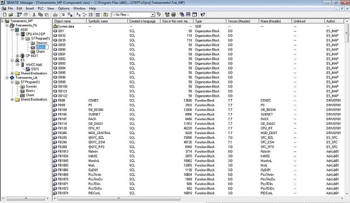
• Component View – this View represents the physical location in the memory of each object, for example, charts and blocks. In Component View, you can immediately see which blocks and CFCs belong to each AS (Automation System - default name given to each 400 CPU in the system).
>
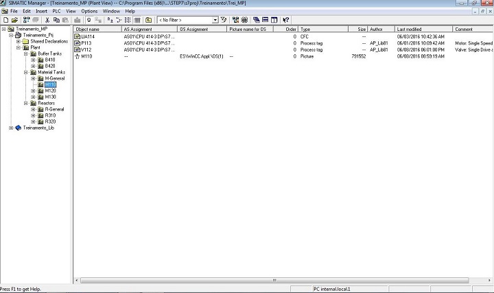
• Plant View – this View shows the exact hierarchical structure of your plant. You can divide the plant into units and see which charts and pictures belong to each unit.
>
• Process Object View – this View shows details of Plant View objects. It is particularly appropriate when you want to associate a same parameter value to a large number of objects or if you want to add a same comment or make the same interconnections for those objects.
>
All operations you perform on Simatic Manager are automatically saved by PCS 7.
How to open Simatic Manager?
You can open Simatic Manager in two ways:
1 – Double-click the STEP 7 icon on your desktop.
2 – In the Start menu on SIEMENS SIMATIC products, select the SIMATIC Manager menu command.
When you start Simatic Manager, the project that you are had previously opened will be automatically loaded.
General
In common
Projects and libraries have some things in common. They are:
• an organized set of data;
• stored in a private folder that includes files and sub-folders;
• maintained by Simatic Manager and its related tools.
Differences
Differences between projects and libraries:
• projects contains the data of at least one (specific programmable application/configurable equipment);
• libraries contain predefined functions to be used in projects.
Station
In a Simatic PCS 7 project a station can be:
• PC (Simatic PC Station) for engineering (ES) or operation (OS - Operator System);
• An Automation System (AS - SIMATIC 400 Station).
Different types of libraries
Libraries are used to save components reusable. The program component can be copied to the existing project library or created directly in a library regardless of projects.
>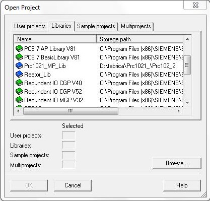
Libraries are structured in a hierarchy similar to projects:
• libraries can contain S7 programs;
• an S7 program can contain exactly one "Blocks" folder, a "Charts" folder and a "Symbols" object (symbol table);
• the "Blocks" folder contains the blocks that are unloaded for the S7 CPU;
• the "Source Files" folder contains the source files of the programs created in different programming languages;
• the "Charts" folder contains the CFC charts.
>
Initial configuration of SIMATIC Manager
Menu Options - Customize...
General
>
• Project storage location/multiprojects (and libraries). The default is C:\Program Files (x86)\SIEMENS\STEP7\s7proj.
Language
>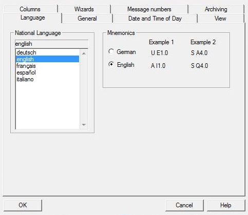
• Selection of the language used in the project.
Archiving
>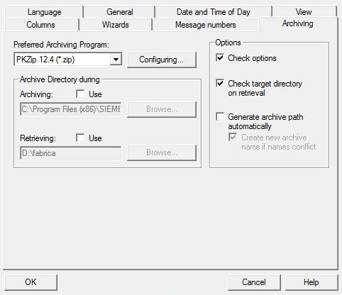
• Select the preferred compaction program and the location of backup/restore directories
Wizards
>
• Enable wizards related to PCS 7
Date and Time of Day
• Choose format for day and time
View
• Simatic Manager viewing options
Message numbers
• Association of the number of messages to the CPU or project
Multiproject
In PCS 7 we must use the multiproject structure. It allows you to link various projects and libraries.
>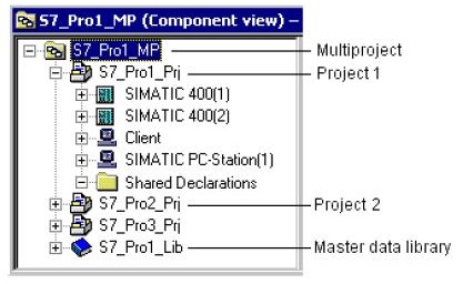
Master Data Library
In a PCS 7 multiproject, a library must be defined with Master Data Library. It will contain the specific patterns of the multiproject and will support the Import/Export of process tags (IEA).
Distributed Engineering
Multiproject facilitates distributed development, with several programmers working together. Each multiproject project can be directed to a different computer.
Automation Licence Manager
Manages the licenses installed on the station.
>
>

Before installing PCS 7 on your computer or in a virtual machine, it is recommended that the computer name be changed to ES.
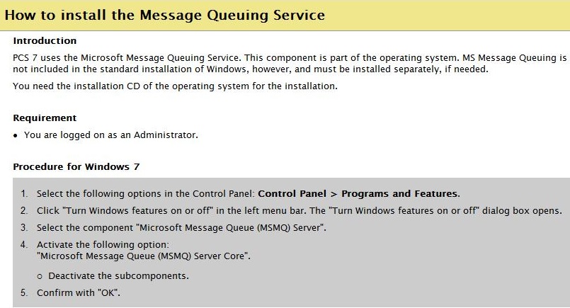
Enable Messaging Queuing Service in Windows 7. Prerequisite for installing PCS 7 (WinCC).
>
>
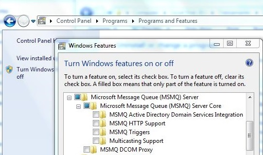
With PCS 7 properly installed (licenses), start developing a application.
Watch on Youtube
System ID
The purpose of the "System ID" is to provide transparency and to enable most efficient technical support.
"System ID" is a unique key to identify a specific PCS 7 System based on end-customer, location, plant, and production unit. It does not change over the lifetime of the PCS 7 System. It is linked to all offers, orders, service contracts and so on.
Type of process
There are two process types:
• Continuous process
Process sequence in plants in which "the same product" is produced "unchanged" (e.g. water desalination plants). Such processes can be automated by PCS 7 using sequential control system (SFC). The automation can be implemented for small plant units as well as for the entire plant.
• Discontinuous (batch) process
Process sequence in plants in which "different products" are produced (e.g. various recipes for producing tablets or mixing paints). Such processes can be automated by PCS 7 using SIMATIC BATCH. With the recipe-based control strategies in SIMATIC BATCH, the process sequences of a PCS 7 plant can be flexibly adapted to changing products, material properties, plant conditions, product stages, etc.
Components of a PCS 7 system
PCS 7 offers a range of options for implementing automation tasks. The large selection and variety of components facilitates the following:
• Employment of suitable components for special requirements
• Selection of components that can be configured exactly to meet specific requirements
The following tables lists optimally matched systems, components and functions for specific process control requirements.
| Prompt | Specification | Item |
|---|---|---|
| Operation and monitoring | Operation and monitoring in process mode | PCS 7 Operator Station with WinCC software |
| Operator control and monitoring via the Internet/Intranet | Use of the operator control and monitoring functions in process mode via the Internet or Intranet | PCS 7 Web server and PCS 7 Web client |
| Access to process data via the Internet/Intranet | Data communication with external systems via OPC and OLE DB | OpenPCS 7 |
| Monitoring the PCS 7 plant | Monitoring the process control | PCS 7 maintenance station |
| Lifebeat monitoring | Monitors systems connected on the terminal bus and system bus | Function "Lifebeat monitoring" from WinCC |
| Time synchronization | Central time synchronization from systems connected on the terminal bus, system bus, and field bus | "Time synchronization" function from WinCC |
| Short-term archiving | Short-term archiving of process values and messages | Archive systems of WinCC |
| Long-term archiving | Use of a PC station for long-term archiving of process values, messages and BATCH data | Process Historian |
| Controlling and operating sequential control systems | Graphically displaying and operating configured sequential control systems | SFC Visualization |
| Operating and monitoring of the Safety Matrix | Display and operation of configured safety reactions | Safety Matrix Viewer |
| Access protection | Central user management, access protection and electronic signatures | SIMATIC Logon with Electronic Signature |
| Batch processes | Controlling discontinuous processes | SIMATIC BATCH |
| Route control | Control, monitoring and diagnostics of material transports in piping systems | SIMATIC Route Control |
| Archived process data | Analysis of process data from archives | Using Process Historian: OS and Information Server; Without using the Process Historian: OS. |
| Prompt | Specification | Item |
|---|---|---|
| Availability | Using high availability automation systems | S7-400H with distributed I/O (e.g. ET 200...) |
| Failure safety | Using fail-safe automation systems | S7-400F with distributed I/O (e.g. ET 200...) |
| Availability and failure safety | Use of high availability and fail-safe automation systems | S7-400FH with distributed I/O (e.g. ET 200...) |
| Control modes | Modules with controller functions | S7-400 FM |
| Distributed I/O | Connecting field devices via PROFIBUS DP depending on the degree of protection, connections, and Ex zone; Connecting distributed I/O via PROFINET I/O; Connecting field devices via PROFINET | Basis ET 200... |
| Sensors and actuators | Connecting actuators and sensors | PROFIBUS PA, PROFINET I/O, FOUNDATION Fieldbus |
| Profibus Intelligent field devices | Connecting intelligent field devices with PROFIBUS communication | PROFIBUS DP/PA PROFINET (via IE/ PB‑Link or CFU) |
| Hart Intelligent field devices | Connecting intelligent field devices with HART communication | Distributed IO system (via PROFIBUS DP or PROFINET IO) |
| Foundation Fieldbus Intelligent field devices | Connecting intelligent field devices to the FOUNDATION Fieldbus | Compact FF Link |
| Coupling DP/PA | Gateway between PROFIBUS DP and PROFIBUS PA | DP/PA coupler, PA-Link |
| Coupling DP/FF | Gateway between PROFIBUS DP and Foundation Fieldbus | Compact FF Link |
| Coupling PROFINET/PA | Gateway between PROFINET and PROFIBUS PA | CFU, IE/PB Link PN IO with downstream DP/PA coupler. |
| Non-redundant PROFIBUS DP devices | Connecting non-redundant PROFIBUS DP devices to redundant PROFIBUS DP | Y-Link |
| Diagnostics (with hardware components) | Simple diagnostics for communication errors in PROFIBUS DP lines | e.g. Diagnostic Repeater |
| Diagnostics (with software components) | Using and activating the PCS 7 diagnostic functions | e.g. NCM S7 PROFIBUS diagnostics |
| Hazardous area | Special I/O components for use in hazardous areas (zones 1 or 2) | S7-300 Ex I/O modules, ET 200iSP. |
| Plant changes | Changing configuration of AS components in RUN | CiR/H-CiR |
| Plant changes | Changing interface of AS blocks in RUN | CPU 410-5H as of firmware version 8.1 or higher |
| Prompt | Specification | Item |
|---|---|---|
| Communication (network) | Terminal bus, system bus | Ethernet |
| Communication (network) | Support for communication through network components such as CPs, bus links | Network components of SIMATIC NET |
| Connecting AS | Connecting automation systems to the system bus | CP 443-1 or internal PROFINET interface of the CPU |
| Connecting OS/BATCH | Connecting PCS 7 operator/BATCH stations to the terminal bus or system bus | Communication processor or other Ethernet connection |
| Connecting ES | Connecting the PCS 7 engineering station to the terminal bus or system bus | Communication processor or other Ethernet connection |
| Point-to-point coupling | Communication between the AS and other stations via point-to-point link | S7-400 CP, S7-300 CP (in ET 200M) |
| Prompt | Specification | Item |
|---|---|---|
| Scalability | Licenses for various numbers of process objects | Licenses |
| Basic engineering | Basic engineering of hardware, communication | STEP 7 with HW Config, NetPro |
| Continuous automation functions | Graphical configuration of automation functions | CFC |
| Discontinuous automation functions | Graphical configuration of sequential control systems with step-enabling conditions | SFC |
| Recurring technological functions | Using the PCS 7 library for technological functions | PCS 7 Advanced Process Library |
| User function blocks, custom | Create your own user function blocks in accordance with IEC 61131-3 | SCL |
| Batch processes | Configuring recipes and batches (production jobs) | SIMATIC BATCH |
| Route control | System for the configuration, control, monitoring and diagnostics of material transports in piping systems | SIMATIC Route Control |
| Availability with S7‑400H | Engineering for redundant automation systems | S7 H Systems |
| Failure safety with S7‑400F | F programming tool with F-function blocks | S7 F Systems |
| Safety reactions to defined states | Assignment of precisely defined reactions to events occurring in the process | Safety Matrix |
| Controller optimization | System-aided optimization of control circuits with PCS 7 | PCS 7 PID Tuner |
| Plant pictures for PCS 7 OS | Creation of plant pictures for the OS in process mode and interconnection of picture objects with single control units (dynamic display) | Graphics Designer of WinCC |
| Logical operations of the Logic matrix | Implementing the control signals. It provides logical operators for the following functions: Permit, Protection and Interlock | Logic Matrix |
| Intelligent field devices | Configuration, parameter assignment, and commissioning of field devices | SIMATC PDM |
| Efficient engineering | Functions for efficient engineering: Working with the several project engineers; Type definitions with reusability and centralized modification capability | Multiproject, SFC type, process tag type, model, control module type, process object view |
| Mass data processing | Creation: Process tags from process tag types; Replicas of models | Import/export assistant, PCS 7 Advanced ES |
| Comparing project versions | Determining differences between various versions of a project | Version Cross Manager (VXM) |
| Versioning | Versioning of multiprojects, projects or libraries | Version Trail |
| Reading parameters back | Automatic cyclic reading of the parameters from the AS | Version Trail |
| Testing | Functional testing of the configuration with a simulated SIMATIC S7 station | S7-PLCSIM |
| Administration | Software administration and lifecycle management | SIMATIC Management Console |
| Plant documentation | Documenting plants in PCS 7 projects in conformance with standards | DOCPRO |
Next
Unregistered user. Buy the training at jats.com.br.