Reactor Project
The Reactor project contains an R310 reactor. This reactor is fed with three different types of products stored in tanks M110, M120 and M130 (Material Tanks). The reactor product is discharged into a B410 tank (Buffer Tank).
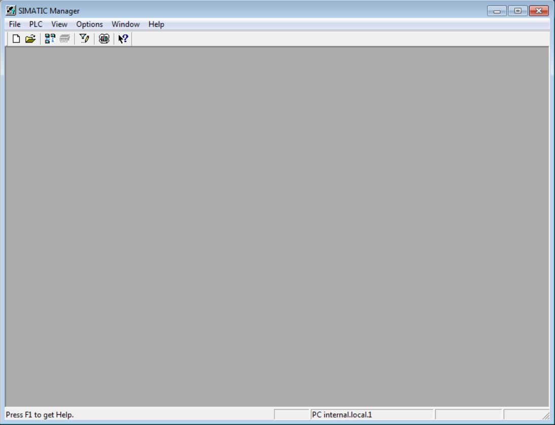
• Open SIMATIC Manager.
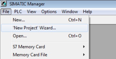
• Select File > New Project Wizard... to create the project.
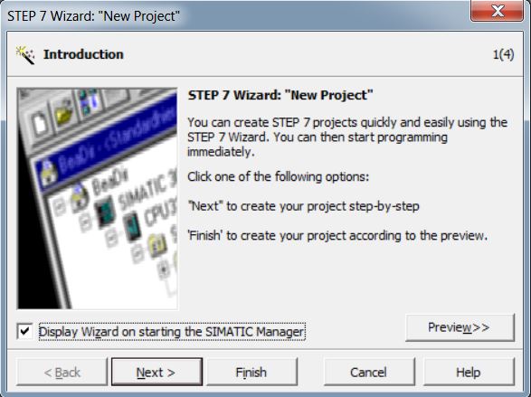
• On the Introduction page, click the Next button.
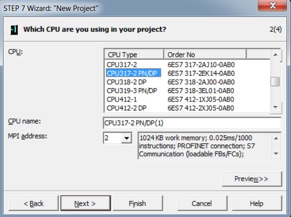
• Select CPU317-2 PN/DP 6ES7 317-2EK14-0AB0. Click the Next button.
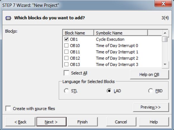
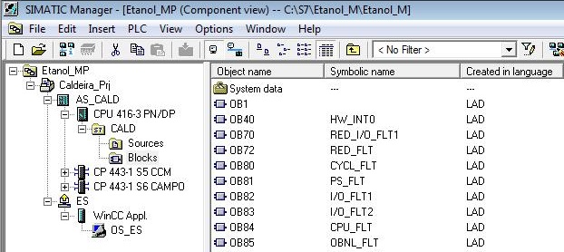
• Add the following OB organization blocks to the project. Select the LAD language. Click the Next button.
| OB1 | HW_INT0 |
| OB80 | CYCL_FLT |
| OB81 | PS_FLT |
| OB82 | I/O_FLT1 |
| OB83 | I/O_FLT2 |
| OB84 | CPU_FLT |
| OB85 | OBNL_FLT |
| OB86 | RACK_FLT |
| OB87 | COMM_FLT |
| OB88 | BREAKUP ERROR |
| OB100 | COMPLETE RESTART |
| OB121 | PROG_ERR |
| OB122 | MOD_ERR |
• Set the project name to Reactor_Prj. Click the Finish button.
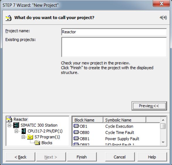
Reactor_Prj project created. The project has been saved to the default storage location (C:\Programs Files (x86)\SIEMENS\STEP7\s7proj).
HW Config
HW Config is the place where the hardware configuration of the SIMATIC Station (AS) is made.
To open HW Config, double-click on AS > Hardware.
HW Config open. The Hardware Catalog appears in the right corner. To allow visibility of Hardware Catalog, select View > Catalog. Components must be selected in the Hardware Catalog and dragged to the main HW Config window. In the image below, two ET200M remotes have been added.

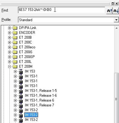
To easily find the component you want within the catalog, enter the component code in the Find text box.
Reactor Project
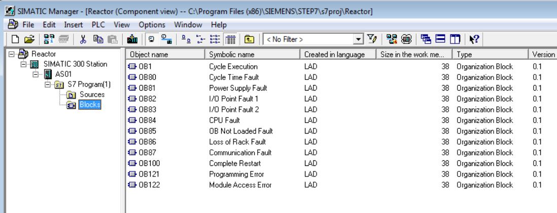
• Rename SIMATIC 300 STATION station to AS01.
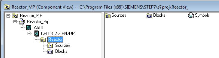
• Rename S7 Program to Reactor.
• Open AS01 HW Config (Hardware). Select AS01 in the tree and double-click on Hardware.
• In the hardware, there is a Rail already inserted (Profile Standard > SIMATIC 300\RACK-300).
Note: To easily find the component you want within the catalog, enter the component code in the Find text box.
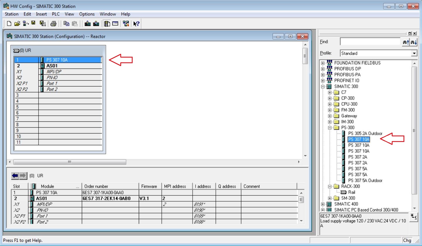
• Insert PS 307 10A 6ES7 307-0KA00-0AA0 power supply into slot 1 (catalog - Profile Standard > SIMATIC 300\PS-300). Click with the mouse on the position in the rack to insert power supply (slot1). Then double-click on the catalog item to be inserted.
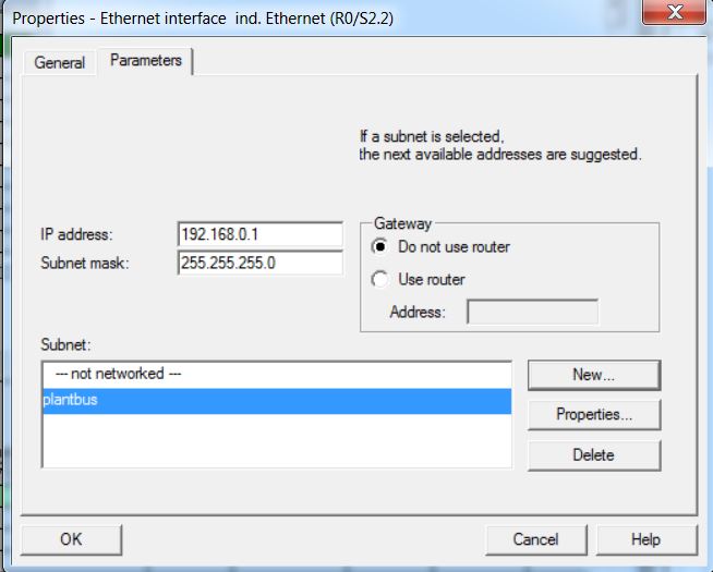
• Double click on slot 2 X2 to configure the IP address and subnet of the CPU.
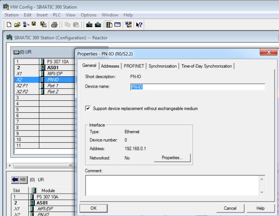
• Set the IP Address of the Ethernet interface R0/S2.2 of the CPU - IP 192.168.0.1 and Mask 255.255.255.0.
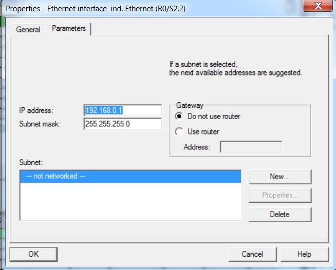
• Create plantbus subnet. Click on New... button and insert plantbus name.
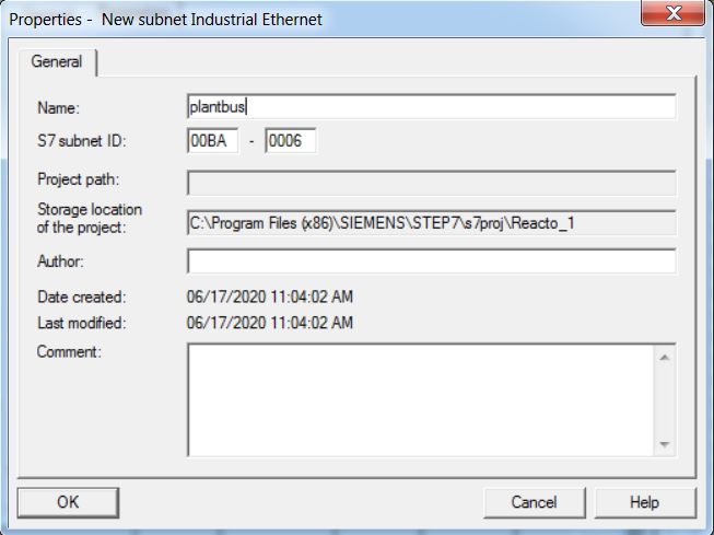
• Select plantbus subnet an click on OK button.
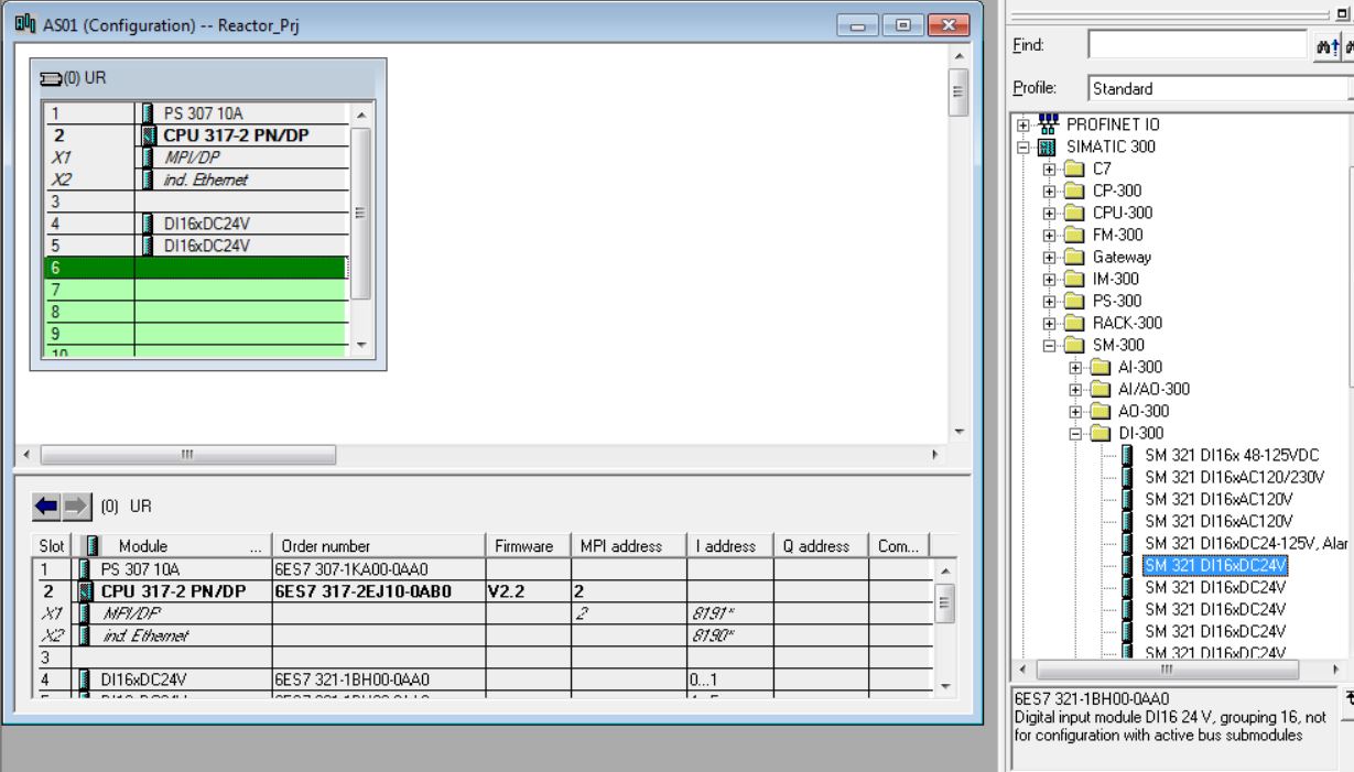
• Insert 2 modules of 16 SM 321 DI16x24VDC digital inputs into slots 4 and 5 (catalog - Profile Standard > SIMATIC 300\SM-300\DI-300). Select 6ES7 321-1BH00-0AA0 and drag to slot 4 of the rack. Repeat procedure for slot 5.
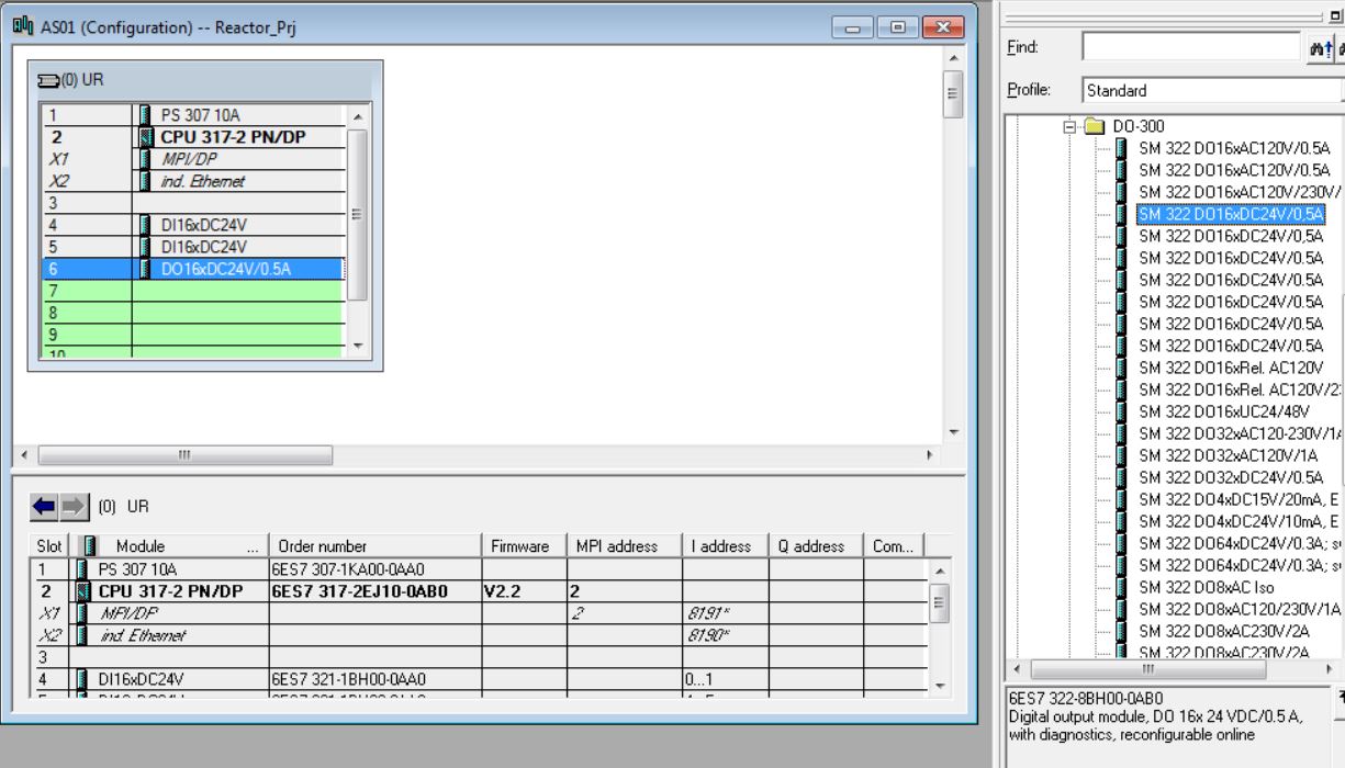
• Insert 1 module of 16 digital outputs SM 322 DO16x24VDC/0.5A into slot 6 (catalog - Profile Standard > SIMATIC 300\SM-300\DO-300). Select 6ES7 322-8BH00-0AB0 and drag to slot 6 of the rack.
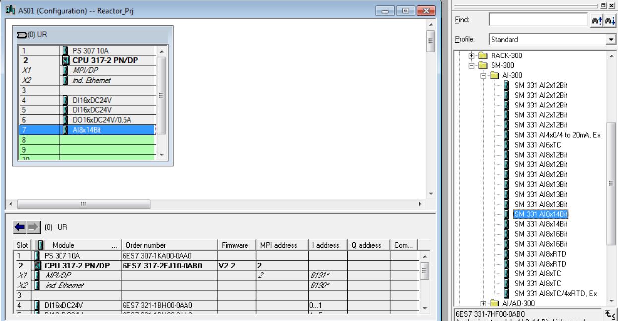
• Insert 1 module of 8 analog input SM 331 AI8x14Bit into slot 7 (catalog - Profile Standard > SIMATIC 300\SM-300\AI-300). Select 6ES7 331-7HF00-0AB0 and drag to slot 7 of the rack.
• Insert 1 modules of 4 analog outputs SM 332 AO8x16Bit in slot 8 (catalog - Profile Standard > SIMATIC 300\SM-300\AO-300). Select 6ES7 332-5HF00-0AB0 and drag to slot 8 of the rack.
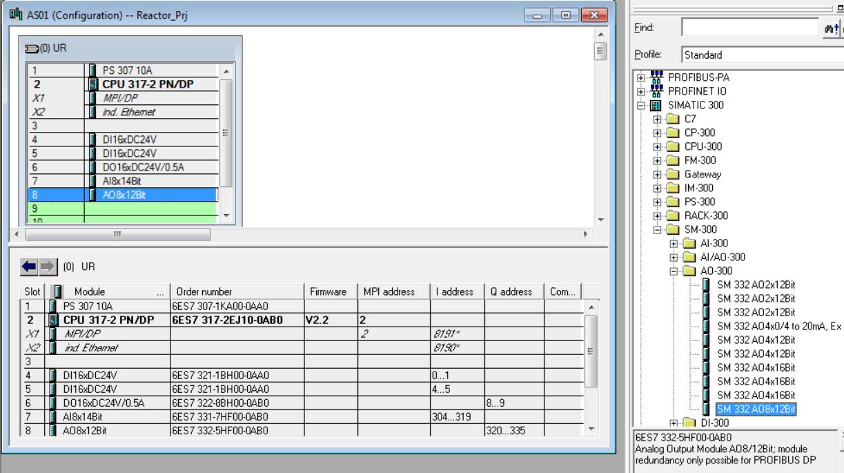
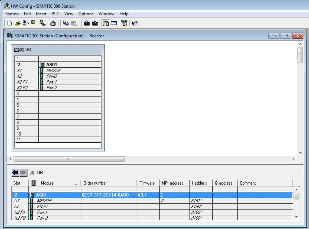
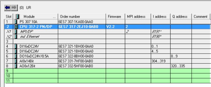
• Observe the input and output addresses generated automatically by the system. These addresses can be changed by the programmer.
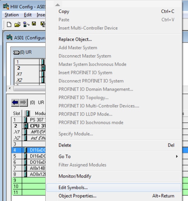
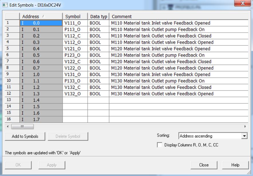
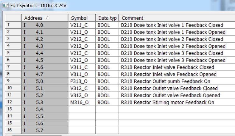
• Edit symbols of the input and output modules. Right-click on slot 4 digital input module and select Edit Symbols...
• Edit slot 4 digital input module symbols.
• Edit slot 5 digital input module symbols.
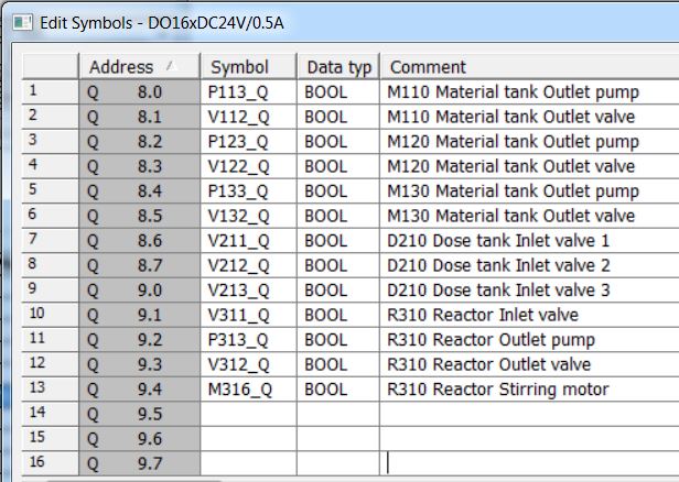
• Edit slot 6 digital output module symbols.
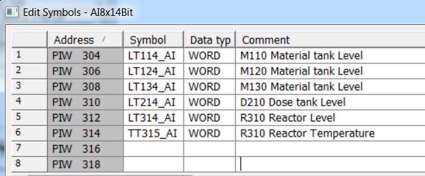
• Edit slot 7 analog input module symbols.
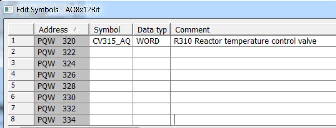
• Edit slot 8 analog output module symbols.
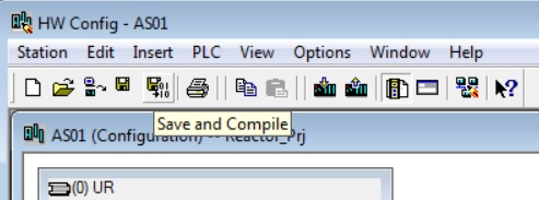
• Save and compile the hardware by clicking the Save and Compile button.
• Close HW Config.
Step 7
What is a STEP 7 project?
In addition to other things, a STEP 7 project includes the following objects:
• Hardware Configuration
• Blocks
These objects are always included, regardless of the number of operating stations, modules and network.
What is included in STEP 7?
You create the project at an engineering station (ES). Several applications are contained in the ES. All applications feature a graphical user interface (GUI) to simplify operation and clearly show the configured data.
• Simatic Manager is the central application and the link portal for all other applications that you will use to create your entire project.
• HW Config contains the configuration of all system hardware, such as CPUs, power sources, communication cards.
• WinCC OS is the tool to configure the OS (operation station).
What is Simatic Manager?
Simatic Manager represents the central application within the system and is used to access all other applications that you need to configure your project. Simatic Manager and all other applications are interconnected.
What is the basic structure of Simatic Manager?
Simatic Manager has a structure similar to Windows Explorer:
• on the left side of the window, you will see the tree-shaped structure showing different objects, depending on the selected View.
• on the right side of the window, you will see details of the objects you have selected in the tree structure.
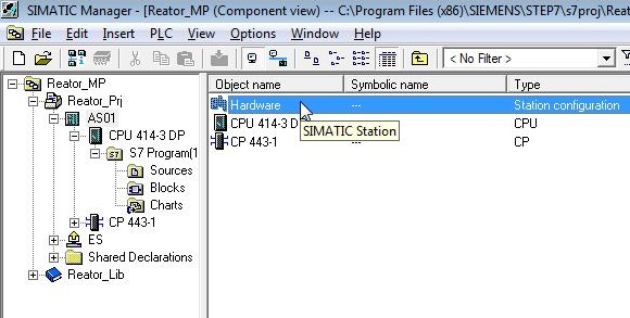
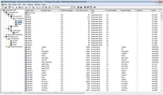
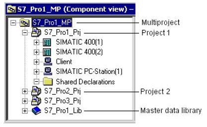
• Component View – represents the physical location in the memory of each object, for example, blocks. In Component View, you can immediately see which blocks belong to each AS (Automation System - default name given to each CPU in the system).
All operations that you perform in Simatic Manager are automatically saved on the system.
How to open Simatic Manager?
You can open Simatic Manager in two ways:
1 – Double click on the STEP 7 icon on your desktop.
2 – From the Start menu on SIEMENS SIMATIC products, select the SIMATIC Manager menu command.
When you start Simatic Manager, the project you had previously opened will be loaded automatically.
Project
Projects are:
• an organized set of data;
• stored in a private folder that includes files and subfolders;
• maintained by Simatic Manager and its related tools.
• projects contain data from at least one station (specific programmable application/configurable equipment);
Station
In a Simatic project a station can be:
• a PC (Simatic PC Station) for engineering (ES) or operation (OS - Operator System);
• an Automation System (AS - SIMATIC 400 Station, for example).
Projects are structured with the following hierarchy:
• can contain S7 programs;
• an S7 program contains exactly one “Blocks” folder and one “Sources” folder;
• the “Blocks” folder contains the blocks that are downloaded to the S7 CPU;
• the “Source Files” folder contains the source files of the programs created in different programming languages;
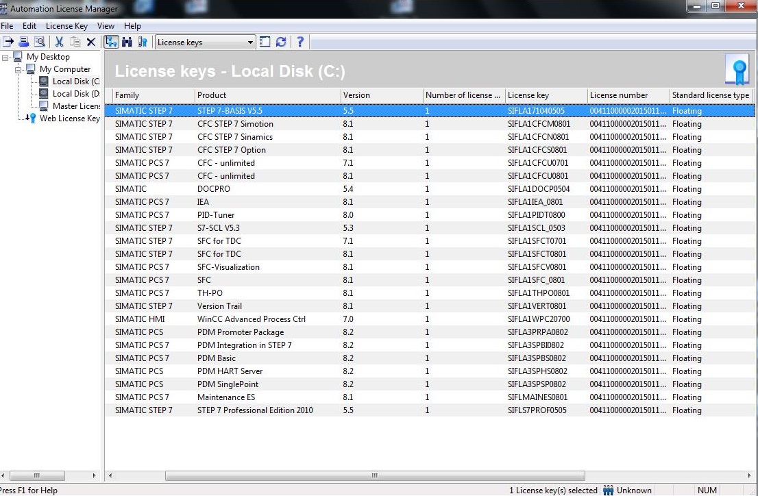
Automation Licence Manager
Manages licenses installed on the station.
Options – Customize... Menu
General
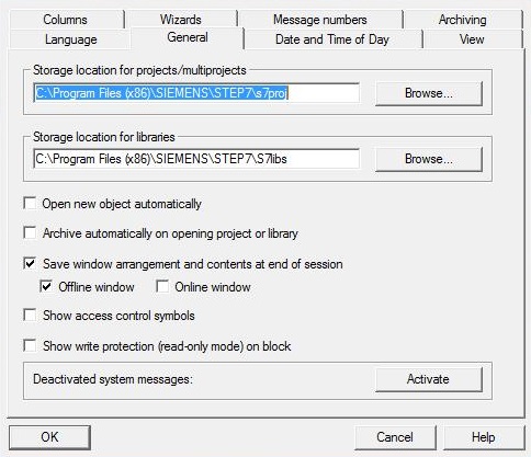
• Project/multiproject storage location (and libraries). The default is C:\Program Files (x86)\SIEMENS\STEP7\s7proj.
Language
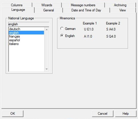
• Selection of the language used in the project.
Archiving
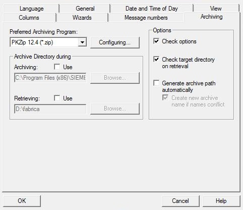
• Select the preferred compaction program and the backup/restore directories location
Date and Time of Day
• Choice of format for day and time
View
• Simatic Manager viewing options
Message numbers
• Association of the number of messages to the CPU or project
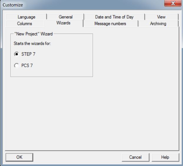
Wizards
• Select the STEP 7 option for the wizards.
Multiproject
It is recommended to use the multi-project structure. It allows you to link different projects and libraries.
Distributed Engineering
The multi-project facilitates distributed development, with several programmers working together. Each multiproject project can be directed to a different computer.
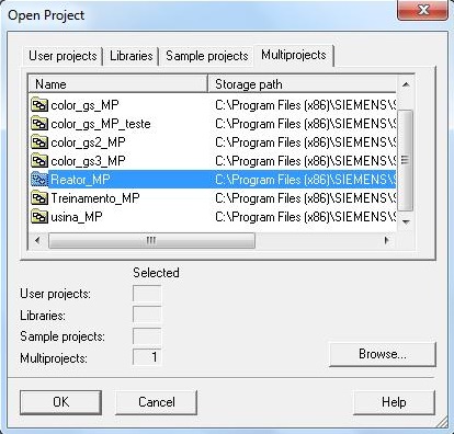
Opening and closing a multiproject
To open a multiproject, open the File menu of SIMATIC Manager and choose the option Open... In the Multiproject tab, choose the desired multiproject.
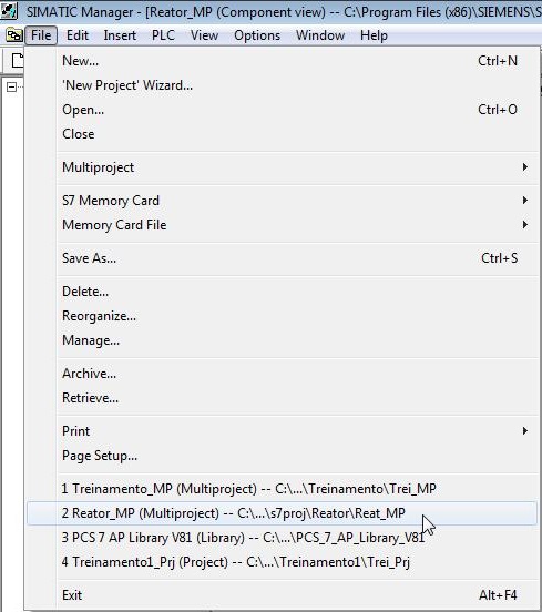
The last multiprojects, projects or open libraries appear at the end of the File menu to be reopened.
To close a multi-project, choose from the File menu of SIMATIC Manager the Close option.
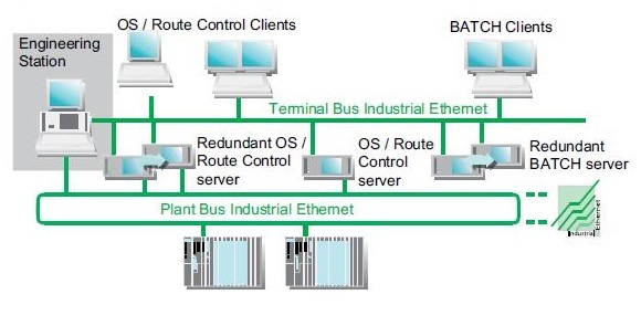
Architectures
• Single station system – ES and OS on the same station.
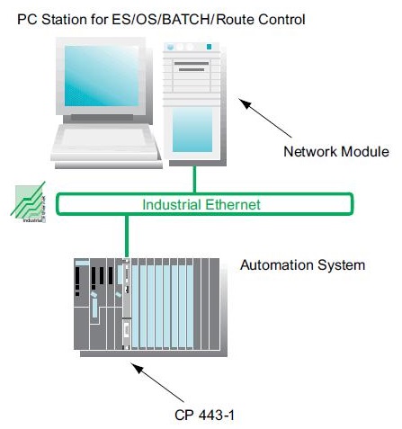
• Multiple station system – ES, OS and client stations on different stations (server/client architecture)
• Multiple station system reduntant – ES, OS and client stations on separate stations with server redundancy (OS).
Unregistered user. Buy the training at jats.com.br.