SIEMENS SIMATIC S7 + WINCC
Micromaster Frequency Inverter
Micromaster
Micromaster is a set of frequency inverters that control the speed of three-phase AC motors. Its various models cover an input range of 120 W single-phase to 11 kW three-phase.
Inverters use the state of the art of Insulated technology Bipolar Gate Transistor (IGBT). A special method of pulse size modulation with adjustable pulse frequency allows quiet control of the motor. Special functions provide protection to the inverter and the motor.
Micromaster Profibus Optional Board
The Profibus-DP communication card function provides a connection between Micromaster drives and high level automation systems.
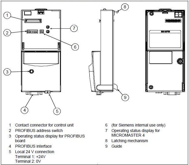
Functionalities:
• Process of cyclic data exchange (PZD) in conformity with PROFIdrive Profile.
• Parametric cyclic access (PKW) or acyclic access to parameters (data block 47) in accordance with PROFIdrive Profile.
• Others.
Communication with Micromaster via Profibus-DP
The following image presents an overview of the functions of Profibus-DP communication implemented in the Micromaster.
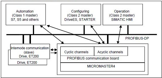
Micromaster cyclic data via Profibus-DP
The Micromaster is controlled via the Profibus-DP cyclic channel. This same channel is used for parameterization.
The user data structure for the cyclic channel is defined in the PROFIdrive profile and is referred to as Parameter Process data Object (PPO). The PROFIdrive profile defines the user data structure with which a master can access slave disks with the cyclic data communication method.
User data structure for PPO
The user data structure for cyclic data traffic is divided into the areas that are transmitted in each telegram:
• Process data area (PZD), that is, control words and setpoints or status information or current values.
• Parameter area (PKW) for reading and writing parameters.
The telegrams for cyclic data transmission have the following basic structure:

Five types of PPO are defined according to the PROFIdrive profile:
• User data without parameter area, with two or six words of Process data or
• User data with parameter area, with two, six or ten words of Process data.

Control and status words
Controlword 1
Control word 1 (bits 0-10 profile PROFIdrive and bits 11-15 specific to the Micromaster).
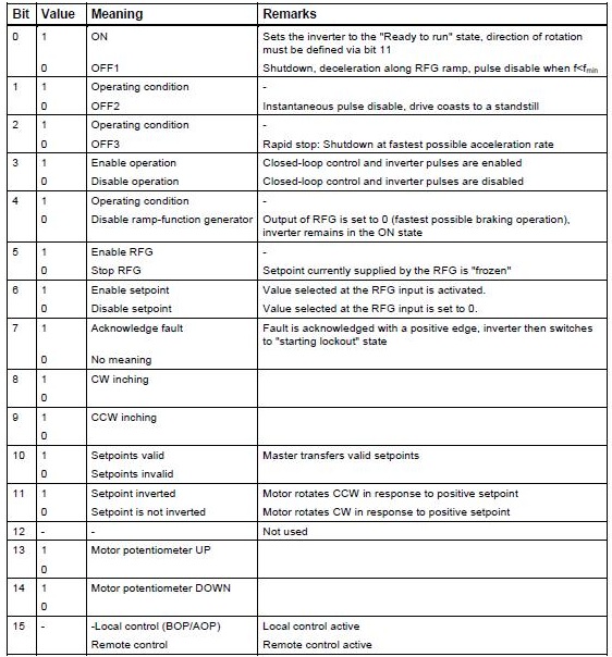
Standard assignment to the word 2 control

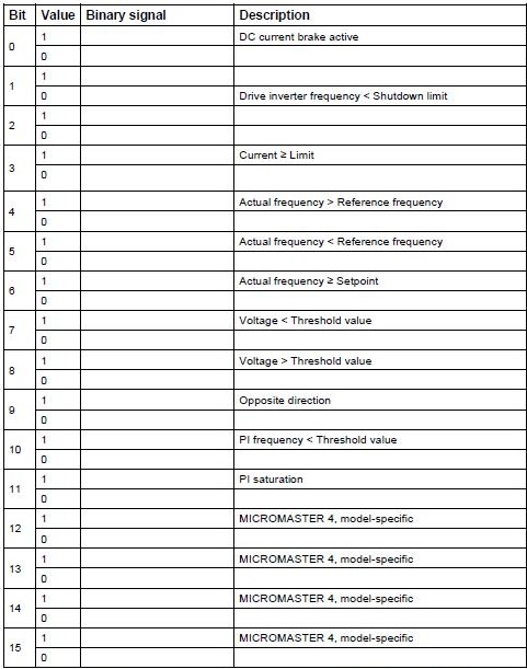
Status word 1
Status word 1 (bits 0-10 profile PROFIdrive and bits 11-15 specific to the Micromaster).
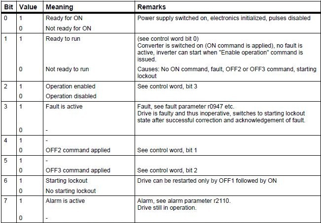
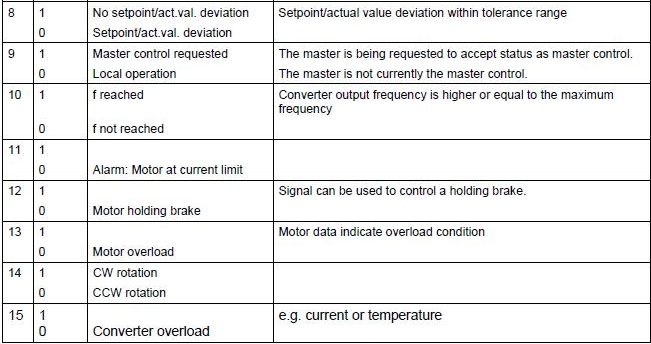
Standard assignment to status word 2
Boiler Project
• Create Function Block for Micromaster frequency inverter. Right-click on the Blocks folder and select Insert New Object > Function Block menu item.
• Set Symbolic Name to FB_MMASTER, Symbol Comment to Micromaster function block and the language to LAD.
• Open function block FB5 FB_MMASTER for editing. In Component View, double-click on the function block.
• In Interface, enter the IN input parameters:
| Name | Type | Description | S7_m_c |
|---|---|---|---|
| IN_BUS1 | DWord | Profibus Input 1 | |
| IN_BUS2 | DWord | Profibus Input 2 | |
| IN_BUS3 | DWord | Profibus Input 3 | |
| RESET | Bool | Reset | |
| LIGA | Bool | FB_MOTOR start/stop command | |
| SETPOINT | Real | Speed setpoint | |
| BASE_VEL | Real | Spped calculation base | |
| BASE_I | Real | Current calculation base | |
| BASE_T | Real | Torque calculation base | |
| BASE_POT | Real | Power calculation base | |
| NO | Int | Profibus DP address | True |
• In Interface, enter the OUT output parameters:
| Name | Type | Description | S7_m_c |
|---|---|---|---|
| OUT_BUS | DWord | Profibus output | |
| RESET | Bool | Reset | |
| LIGADO | Bool | Motor running output | |
| PRONTO | Bool | Inverter ready | True |
| RPM_OK | Bool | Setpoint in tolerance band | True |
| LR | Bool | Local/Remote | True |
| CORRENTE | Real | Current | True |
| VELOCIDADE | Real | Speed | True |
| TORQUE | Real | Torque | True |
| POTENCIA | Real | Power | True |
| COD_FALHA | Real | Fault code (inverter) | True |
• In Interface, enter the IN_OUT parameters:
| Name | Type | Description | S7_m_c |
|---|---|---|---|
| FALHA | Int | Fault code (internal) | True |
• In Interface, enter the STAT parameters:
| Name | Type | Description |
|---|---|---|
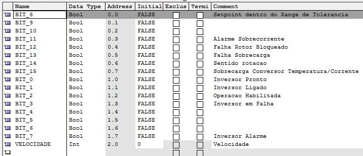
| DADOSENTRADA_1 | Struct | Input data Words 0 and 1 |
Structure:
| Name | Type | Description |
|---|---|---|
| BIT_0 | Bool | Ready for ON |
| BIT_1 | Bool | Ready to run |
| BIT_2 | Bool | Operation enabled |
| BIT_3 | Bool | Fault is active |
| BIT_4 | Bool | |
| BIT_5 | Bool | |
| BIT_6 | Bool | |
| BIT_7 | Bool | Alarm is active |
| BIT_8 | Bool | SP in tolerance range |
| BIT_9 | Bool | |
| BIT_10 | Bool | |
| BIT_11 | Bool | Motor at current limit |
| BIT_12 | Bool | Motor holding brack |
| BIT_13 | Bool | Motor overload |
| BIT_14 | Bool | CW rotation |
| BIT_15 | Bool | Inverter overload |
| VELOCIDADE | Int | Speed |
| Name | Type | Description |
|---|---|---|
| DADOSENTRADA_2 | Struct | Input data Words 2 and 3 |
Structure:
| Name | Type | Description |
|---|---|---|
| CORRENTE | Int | Current |
| TORQUE | Int | Torque |
| Name | Type | Description |
|---|---|---|
| DADOSENTRADA_3 | Struct | Input data Words 4 and 5 |
Structure:
| Name | Type | Description |
|---|---|---|
| POTENCIA | Int | Power |
| CODFALHA | Int | Fault code |
| Name | Type | Description |
|---|---|---|
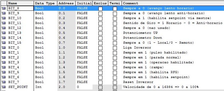
| DADOSSAIDA | Struct | Output data Words 0 and 1 |
Structure:
| Name | Type | Description |
|---|---|---|
| BIT_0 | Bool | ON - Set Ready to run state |
| BIT_1 | Bool | Always 1 (pulse enable) |
| BIT_2 | Bool | Always 1 (without rapid stop) |
| BIT_3 | Bool | Always 1 (enable operation) |
| BIT_4 | Bool | Always 1 (ramp function generator) |
| BIT_5 | Bool | Always 1 (enable RFG) |
| BIT_6 | Bool | Always 1 (enable setpoint) |
| BIT_7 | Bool | Acknowledge fault |
| BIT_8 | Bool | Always 0 (without CW inching) |
| BIT_9 | Bool | Always 0 (without CCW inching) |
| BIT_10 | Bool | Always 1 (setpoint via master) |
| BIT_11 | Bool | Setpoint is not inverted |
| BIT_12 | Bool | Always 0 (not used) |
| BIT_13 | Bool | Motor potenciometer Up |
| BIT_14 | Bool | Motor potenciometer Down |
| BIT_15 | Bool | Always 0 (1 – Local/ 0 – Remote) |
| SET_POINT | Int | Speed reference 0 to 16384 => 0 to 100% |
| Name | Typo |
|---|---|
| bs1 | Bool |
| bs0 | Bool |
| SETPOINT_INT | Int |
| SETPOINT_REAL | Real |
| AUX_CORRENTE_DI | DInt |
| AUX_CORRENTE_REAL | Real |
| BASE_I | Real |
| AUX_SET_POINT | Real |
| AUX_SET_POINT_DI | DInt |
| AUX_DINT_VELOCIDADE | DInt |
| AUX_TORQUE_DI | DInt |
| AUX_VELOCIDADE_REAL1 | Real |
| AUX_TORQUE_REAL1 | Real |
| AUX_VELOCIDADE_REAL2 | Real |
| AUX_TORQUE_REAL2 | Real |
| AUX_CORRENTE_REAL2 | Real |
| AUX_POTENCIA_DI | DInt |
| AUX_POTENCIA_REAL1 | Real |
| AUX_POTENCIA_REAL2 | Real |
• Insert logic for Micromaster.
The Micromasters in the project were defined with telegram 0 PKW, 6PZD (PPO 4), with 6 words of reading (coming from Micromaster) and 6 words of writing (going to Micromaster).

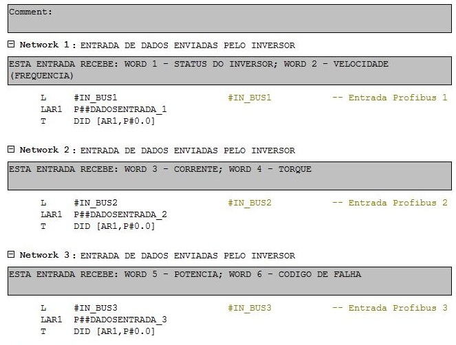
Networks 1, 2 and 3
Data movement of the input parameters IN_BUS1, IN_BUS2 and IN_BUS3 (Micromaster reading words) for the struct parameters DADOSENTRADA_1, DADOSENTRADA_2 and DADOSENTRADA_3. STL instructions. Loading of #IN_BUSx in the accumulator (L) and transferring to DADOSENTRADA_x (LAR1 and T).
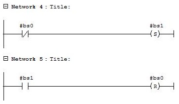
Networks 4 and 5
Auxiliary bits bs0 - always at 0 and bs1 - always 1.
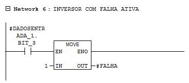
Network 6
Falha = 1 – Inverter with active fault.
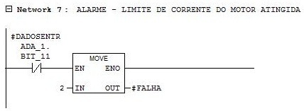
Network 7
Falha = 2 – Motor current limit reached.
Network 8
Falha = 3 – Rotor blocked.

Network 9
Falha = 4 – Motor overload.
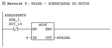
Network 10
Falha = 2 – Inverter overload.

Network 11
Reset of inverter failures.
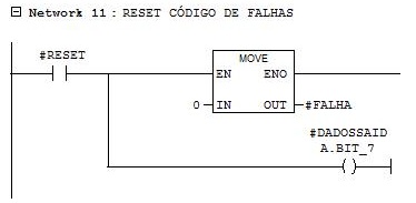
Network 12
Inverter status on.

Network 13
Inverter status ready.
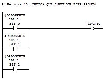
Network 14
Speed setpoint status within the tolerance range.

Network 15
Inverter on/off command.
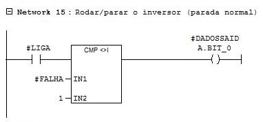
Network 16
Forced bits in 1.

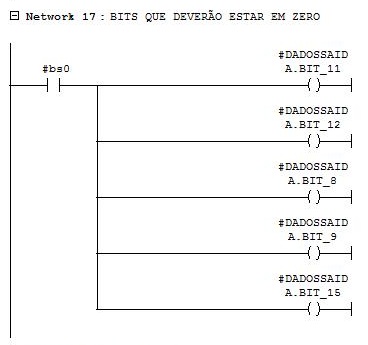
Network 17
Forced bits in 0.
Network 18
Writing the speed setpoint for the inverter. Parameter conversion in real with a range from 0 to 100% to a word with a range from 0 to 16384.

Network 19
Inverter speed reading. Conversion of parameter in word with range from 0 to 16384 to parameter in real in the range of RPM.

Network 20
Motor current reading. Conversion of parameter in word with range from 0 to 16384 for parameter in real of the current (range depends on the motor nominal current).

Network 21
Motor torque reading. Parameter conversion in word with a range from 0 to 16384 for parameter in real torque N.m.

Network 22
Engine power reading. Conversion of parameter in word with range from 0 to 16384 for parameter in real of the power.

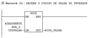
Network 23
Reading the current fault code of the inverter.
Network 24
Data movement from the struct DADOSSAIDA parameter to the OUT_BUS output parameter (words 0 and 1 from writing to inverter). STL instructions.

• Open MOTORS function and insert FB_MOTOR and FB_MMASTER for the MT300 - Forced Air Fan.
| Name | Block | DB | Input | Output |
|---|---|---|---|---|
| MT300 | FB_MOTOR | DB31 | ||
| MT300MM | FB_MMASTER | DB32 | IW534..545 | QW524..535 |
Network 1
FB_MOTOR function block instance for MT300. Response time set for activation and deactivation in 10 seconds.

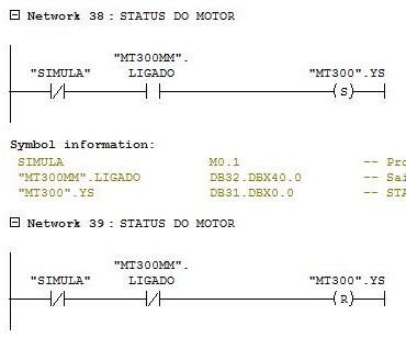
Networks 2 and 3
Moving the status of inverter LIGADO (ON) = 1 and inverter status LIGADO (ON) = 0 from MT300MM to MT300.
Network 4
Force parameter BLQ to 1 to enable the motor to start.

Network 5
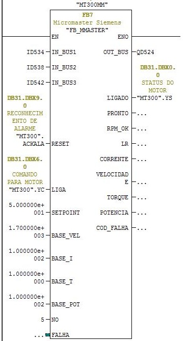
FB_MMASTER function block instance for the MT300.
Input parameters:
IN_BUS1 - receives the address of words 0 and 1 from the inverter reading (ID534).
IN_BUS2 - receives the address of words 2 and 3 from the inverter reading (ID538).
IN_BUS3 - receives the address of words 4 and 5 from the inverter reading (ID542).
RST – alarm and fault reset (MT300.ACKALA).
LIGA – receives YC output parameter from MT300 function block instance.
SETPOINT – speed setpoint.
BASE_VEL – speed in rpm for 60/50 Hz or 100%.
BASE_I – rated current (Ex = 100 A).
BASE_T – torque limit value.
BASE_POT – power limit value.
NO – Profibus DP address (address 5 for MT300).
Output parameters:
OUT_BUS - receives the address of words 0 and 1 from writing to inverter (QD524).
LIGADO – writes the value of the LIGADO (ON) status parameter of the inverter to FB_MOTOR (MT300.YS).
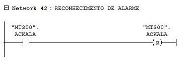
Network 6
Reset of the alarm acknowledgment button activated by the operator.
• Select Operator Control and Monitoring for DB31 and DB32 of the MT300.
• Compile AS and OS.
• Create MICRO.pdl picture with 400 x 200 size.
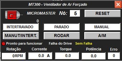
• Insert custom object for MT300 in the process picture.
C script to show the PW_OBJ picture window object in the current picture.

The Picture Name property of the PW_OBJ picture window receives the name of the MICRO.PDL picture.
The TagPrefix property of the PW_OBJ picture window is set to CALD/MT300. This instruction adds the text “CALD/MT300” at the beginning of all dynamizations of objects within the picture window.
• Create custom object for writing motor speed setpoint and reading speed in rpm.

• Insert MT300 alarm messages in WinCC Alarm Logging.
• Compile and download AS. Compile OS and run the project. Test motor.
• Repeat the procedure for the other Micromaster inverters:
| Name | Block | DB | Input | Output |
|---|---|---|---|---|
| MT305 | FB_MOTOR | DB33 | ||
| MT305MM | FB_MMASTER | DB34 | IW546..557 | QW536..547 |
| MT301 | FB_MOTOR | DB35 | ||
| MT301MM | FB_MMASTER | DB36 | IW558..569 | QW548..559 |
| MT302 | FB_MOTOR | DB37 | ||
| MT302MM | FB_MMASTER | DB38 | IW570..581 | QW560..571 |
| MT303 | FB_MOTOR | DB39 | ||
| MT303MM | FB_MMASTER | DB40 | IW582..593 | QW572..583 |
| MT304 | FB_MOTOR | DB41 | ||
| MT304MM | FB_MMASTER | DB42 | IW594..605 | QW584..595 |
| MT101 | FB_MOTOR | DB43 | ||
| MT101MM | FB_MMASTER | DB44 | IW606..617 | QW596..607 |
| MT102 | FB_MOTOR | DB45 | ||
| MT102MM | FB_MMASTER | DB46 | IW618..629 | QW608..619 |
| MT103 | FB_MOTOR | DB47 | ||
| MT103MM | FB_MMASTER | DB48 | IW630..641 | QW620..631 |
| MT104 | FB_MOTOR | DB49 | ||
| MT104MM | FB_MMASTER | DB50 | IW642..653 | QW632..643 |
| MT105 | FB_MOTOR | DB51 | ||
| MT105MM | FB_MMASTER | DB52 | IW654..665 | QW644..655 |
• Insert motors in pictures.