SIEMENS SIMATIC S7 + WINCC
Motor
Boiler Project
• Create Function Block for motor. Right-click on the Blocks folder and select Insert New Object > Function Block menu item.
• Set Symbolic Name to FB_MOTOR, Symbol Comment to Function Block Motor and the language to LAD.
• Open Attributes tab and in line 1 include the attribute S7_m_c with value true. This monitoring and control attribute allows function block tags to be automatically generated in WinCC when the AS is compiled.
• Open FB4 FB_MOTOR for editing. In Component View, double-click on the function block.
• In Interface, enter the IN input parameters:
| Name | Type | Description | S7_m_c |
|---|---|---|---|
| YS | Bool | Motor status | True |
| TRESP | Time | Start/stop limit time |
• Enter the OUT output parameters:
| Name | Type | Description | S7_m_c |
|---|---|---|---|
| YC | Bool | Motor start/stop command | True |
• Enter the IN_OUT input/output parameters:
| Name | Type | Description | S7_m_c |
|---|---|---|---|
| AM | Bool | Auto/Manual | True |
| CR | Bool | Motor manual start command button | True |
| CP | Bool | Motor manual stop command button | True |
| M1 | Bool | Motor did not start alarm | True |
| M2 | Bool | Motor tripped | True |
| M3 | Bool | Motor did not stop alarm | True |
| BLQ | Bool | Motor interlock | True |
| CA | Bool | Motor automatic start/stop command | True |
| ACKALA | Bool | Alarm acknowledment | True |
| MANUT | Bool | Motor in maintenance | True |
| FALHA | Bool | General fault | True |
| ALM | Bool | Alarm | True |
• Enter the STAT parameters:
| Name | Type |
|---|---|
| A1_MT | TON |
| T1 | BOOL |
| P_T1 | BOOL |
| P_T2 | BOOL |
| XA1 | BOOL |
| XA2 | BOOL |
• Insert logic for motor.
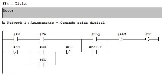
Network 1
Command to run the motor (move 1 to the YC output). The motor starts in two conditions:
• when in manual (AM = 0) and the operator button receives the command rotate (CR = 1). The stop command (CP = 1) for the motor when running in manual.
• when in automatic (AM = 1) and the command in automatic causes it to run (CA = 1).
When in maintenance (MANUT = 1), the interlock (BLQ = 1) is not considered. When the motor goes to alarm, the YC command is set to 0.
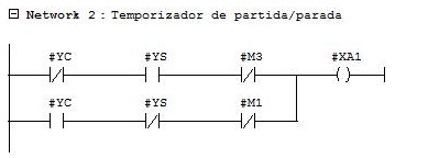
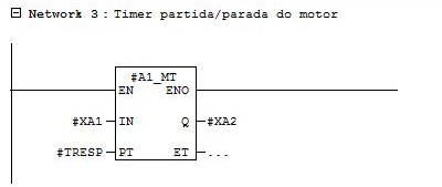
Networks 2 and 3
Timer activated after motor start or stop command.
When starting the motor, the YC (digital output) command goes to 1 and the logic waits for the motor feedback status to go to 1 (YS). If YS does not go to 1 by the time in seconds defined by the TMR parameter, a start fault indication is activated (M1 = 1) and the YC command goes to 0.
When stopping the motor, the YC (digital output) command goes to 0 and the logic waits for the motor feedback status to go to 0 (YS). If YS does not go to 0 by the time in seconds defined by the TMR parameter, a stop fault indication is activated (M3 = 1). The YC command remains at 0.
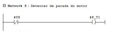
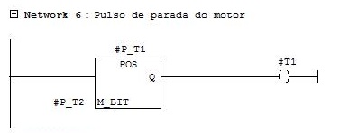
Networks 4 to 7
Faults presented by the motor:
M1 – Motor did not start.
M3 – Motor did not stop.
M2 – Motor tripped. This fault is activated when the command for the motor (YC) is at 1 (motor running) and the YS feedback goes from 1 to 0 (negative transition detection contact). When the motor is stopped via operator command (CM = 1), via automatic command (CA = 1) or via process interlock (BLQ = 0), first the YC command goes to 0 (de-energized) and only afterwards the YS feedback go to 0 (return) as well. When the reverse occurs, YS goes to 0 rather than YC, it indicates a trip (probably overcurrent of the motor).


Network 8
The three types of motor failures, in addition to the general drive failure indication, trigger the ALM variable. This variable when actuated (in 1) prohibits the command for the motor to run (YC always at 0).

Network 9
The ACKALA parameter sends the motor failures to 0.

Networks 10 and 11
Reset of operator control buttons. The manual control buttons for running and stopping the motor (CR and CP) are activated by the operator and deactivated by the PLC immediately after acting on the command logic.
