Motor_Lean
Important
If you have little experience with PLC programming, I recommend that you skip to Appendix - S7 + WinCC Training and then come back at this point (last page of the training).
PCS7 programming makes use of ready-made blocks and their understanding can be difficult for beginners. Study S7 + WinCC, even briefly, especially the function block concept.
The presented part of the S7 + WinCC training contains the development of the Reactor project. This project will be developed in PCS7 and will also serve to compare the programming with and without the PCS7 library.
CFC charts e o CFC Editor
Create CFCs by inserting blocks from PCS 7 Library Vxx into CFCs. This includes simple blocks such as process closed circuit blocks or for monitoring of measured values. The inputs and outputs of these blocks are interconnected and parameters configured directly in the CFC Editor. A friendly interface helps with this task.
In CFC, you work with ready-made blocks that have a specific function. You place these function blocks on the CFC chart, interconnect them, and assign parameters to them.
PCS 7 also provides process tag types in the default library. They represent complete CFCs for multiple process tags, such as motors and valves.
In order to maintain an adequate project structure, CFCs should be created in the appropriate Plant Hierarchy folder. In the example, the M110 folder contains the CFCs LIA114, P113 and V112.

Motor_Lean
The Advanced Process Library (APL) contains a motor drive process tag type template called Motor_Lean.
When you insert a CFC of type process tag type into the system, an instance of this process tag type is created. Therefore, Motor_Lean is a type, a model, and from it, several motors can be created, becoming CFCs. In the Crushing Soy project, the TCR0802A, EL0803A, EL0805A motor CFCs are instances of Motor_Lean.

Motor_Lean commands the motor on/off signal and monitors the motor running/stop return signal.
Instead of creating your own logic for triggering a motor, use Motor_Lean. It is good practice to always use available logics from the PCS 7 library. Over time it is important to PCS 7 library. Because it is very vast, you will hardly need to create your own blocks and process tag types. Still, you will learn how to create your own blocks and process tag types later in the course.
Motor_Lean blocks
Motor – MotL – FB1850

Interconnections:
Input
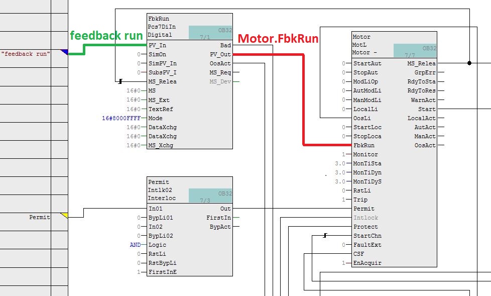
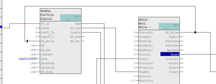
Motor.FbkRun <-- FbkRun.PV_Out (1 = motor running status)
Output
Motor.Start --> OutStart.PV_In (0 = stop motor command; 1 = start motor command)
FbkRun – Pcs7DiIn – FB1871
Interconnections:
Input
FbkRun.PV_In <-- feedback run (1 = motor running status - digital input)
Output
FbkRun.PV_Out --> Motor.FbkRun (1 = motor running status)
OutStart – Pcs7DiOu – FB1816

Interconnections:
Input
OutStart.PV_In <-- Motor.Start (0 = stop motor command; 1 = start motor command)
Output
OutStart.PV_Out --> output start (0 = stop motor command; 1 = start motor command - digital output)
Permit – Intlk02 – FB1824
The Permit parameter of the Motor block (MotL) in Motor_Lean is used to allow or disallow the motor to be controlled via OS (Operator Station).
With logic level 1 (true), motor operation in the OS is allowed. With logic level 0 (false), motor operation is not allowed via OS. The default value of the parameter is logic level 1.
The Perm_En parameter enables or disables the action of the Permit parameter. With logic level 1, Permit is enabled (default).

Interconnections:
Input
Permit.In01 <-- Permit (external condition)
Output
Permit.Out --> Motor.Permit (1 = command allowed in OS)
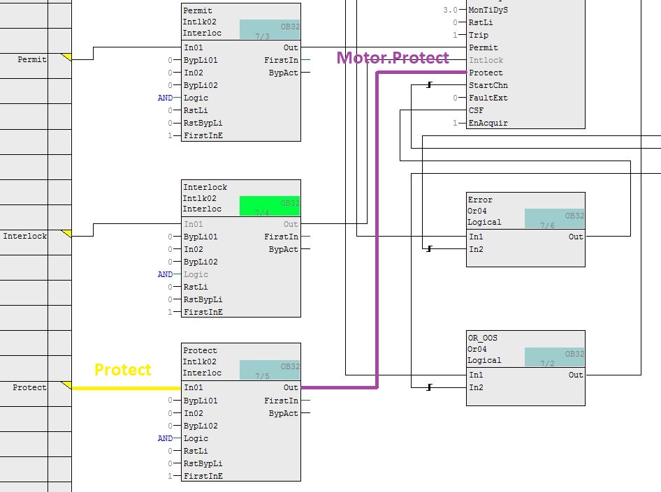
Interlock – Intlk02 – FB1824
The Motor block (MotL) Intlock parameter in Motor_Lean is used to activate or deactivate the interlock without reset.
With logic level 1 (true), Interlock is not activated. With logic level 0 (false), the interlock without reset is activated. The motor can be operated without reset, as long as the interlock condition has disappeared. The default value of the parameter is logic level 1 (disabled).
O parâmetro Intl_En habilita ou desabilita a ação do parâmetro Intlock. Com o nível lógico 1, Intlock é habilitado (padrão).

Interconnections:
Input
Interlock.In01 <-- Interlock (external condition)
Output
Interlock.Out --> Motor.Intlock (1 = interlock without reset)
Protect – Intlk02 – FB1824
The Protect parameter of the Motor block (MotL) in Motor_Lean is used to activate or deactivate the protective interlock.
With logic level 1 (true), Protect is not activated. With logic level 0 (false), the protective interlock is activated. The motor can be operated after a reset, as long as the interlock condition has disappeared. The default value of the parameter is logic level 1 (disabled).
The Prot_En parameter enables or disables the action of the Intlock parameter. With logic level 1, Protect is enabled (default).
Interconnections:
Input
Protect.In01 <-- Protect (external condition)
Output
Protect.Out --> Motor.Protect (1 = protective interlock disabled)
OR_OOS – Or04 – FC364
The OosLi parameter of the Motor block (MotL) in Motor_Lean is used to put the motor out of service via interconnection.
With logic level 1 (true), the motor is out of service. With logic level 0 (false), the motor is running. The default value of the parameter is logic level 0 (motor running).
In Motor_Lean, the OR_OOS block performs an OR logic with two inputs. If one or more inputs have logic level 1, the block output goes to logic level 1. Both inputs indicate whether the field devices are being maintained or not. The devices are the motor status feedback (digital input) and the actuator command (digital output). The output of the OR_OOS block is interconnected with the OosLi input parameter of the Motor block.

Interconnections:
Inputs
OR_OOS.In1 <-- FbkRun.OosAct (1 = field device is under maintenance)
OR_OOS.In2 <-- OutStart.OosAct (1 = field device is under maintenance)
Output
OR_OOS.Out --> Motor.OosLi (1 = motor in out of service mode, via interconnection)
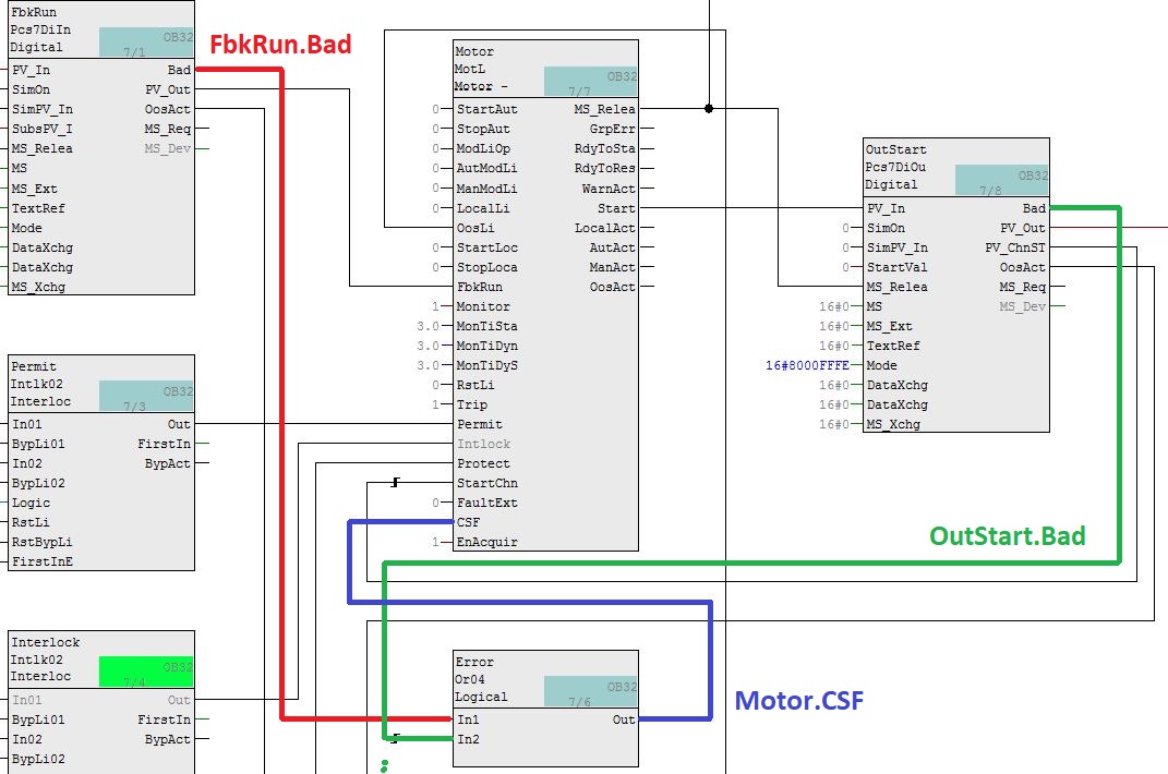
Error – Or04 – FC364
The CSF parameter of the Motor block (MotL) in Motor_Lean is used to indicate an external error (control system error).
With logic level 1 (true), the external error is activated. With logic level 0 (false), there is no external error. The default value of the parameter is logic level 0 (without external error).
In Motor_Lean, the Error block executes an OR logic with two inputs. If one or more inputs have logic level 1, the block output goes to logic level 1. The two inputs indicate whether the field devices have valid process values (parameter Bad). When the Bad output parameter of the FbkRun and OutStart blocks is at logic level 1, it indicates that the process value is not valid. The devices are the motor status feedback (digital input) and the actuator command (digital output). The output of the Error block is interconnected with the CSF input parameter of the Motor block.
Inputs
Error.In1 <-- FbkRun.Bad (1 = process value is not valid)
Error.In2 <-- OutStart.Bad (1 = process value is not valid)
Output
Error.Out --> Motor.CSF (1 = external error)
MotL – motor (Large)
Type + Number: FB1850
Family: Drives
MotL controls a motor with an output signal.
The MotL block must be installed in a cyclic interrupt OB (OB30 to OB38).
MotL operating modes:
• Local mode
The motor is controlled in "Local mode": "Start" (StartLocal = 1) and "Stop" (StopLocal = 1). A block operated in "local mode" is controlled by "local" signals or by feedback signals (input parameters FbkStart = 1).
• Automatic mode
The motor is controlled in "Automatic mode": "Start" (StartAut = 1) and "Stop" (StopAut = 1).
• Manual mode
The motor is controlled in "Manual mode": "Start" (StartMan = 1) and "Stop" (StopMan = 1).
• Out of service
MotL I/Os
Some input parameters:
AutModLi - 1 = "Automatic mode" via interconnection or SFC (controlled by ModLiOp = 1)
AutModOp – 1 = "Automatic mode" via operator (controlled by ModLiOp = 0)
AV – Additional analog input (eg motor current)
CSF – 1 = External error (control system error)
FbkRun – Output return signal. 1 = Start and 0 = Stop
ManModLi – 1 = "Manual mode" via interconnection or SFC (controlled by ModLiOp = 1)
ManModOp – 1 = "Manual mode" via operator (controlled by ModLiOp = 0)
ModLiOp – 0 = Operator and 1 = Interconnection or SFC
SimLiOp – Simulation Activation / Deactivation: 0 = Operator and 1 = Interconnection or SFC
SimOnLi – 1 = Simulation via interconnection or SFC (controlled by SimLiOp = 1)
SimOn – 1 = Simulation on
StartAut – 1 = Start motor in "automatic mode"
StartMan – 1 = Start motor in “manual mode”
StopAut – 1 = Stop motor in “automatic mode”
StopMan – 1 = Stop motor in “manual mode”
Trip – 1 = Motor is in good condition
Some output parameters:
AutAct – 1 = “Automatic mode” enabled and 0 = “Manual mode” enabled
AV_Out = Additional analog input block output
FbkRunOut – Motor start return. 1 = Start and 0 = Stop
ManAct – 1 = “Manual mode” enabled
Run – 1 = Motor is running
Start – 1 = Motor control: started
Stop – 1 = Motor stopped
Faceplate
MotL standard view

1 – Show and select operation mode
2 – Starting and stopping the motor (Start, Stop and Rapid Stop)
3 – Reset block
4 – Block Interlock Functions
Interlock functions of the block are Interlock, Protection and Permission.
5 – Display of auxiliary values
6 – Navigation button
7 to 10 - Area to indicate block states
11 – Automatic preview – indicates the command value for the motor in automatic
12 – Motor status (running/stopped)
Motor status table:

Block icon
MotL block icons table:

Crushing Soybean Project
In the Plant view, a master data library should have the Models folder and Process tag types folder. These folders will not be automatically created after you declare a library as the master data library. However, the two folders will be generated when you create Models and Process tag types.
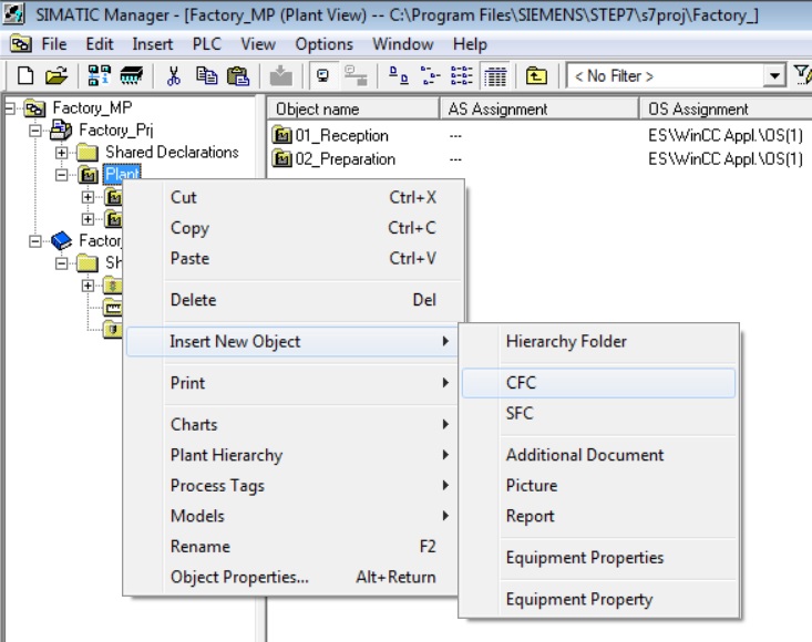
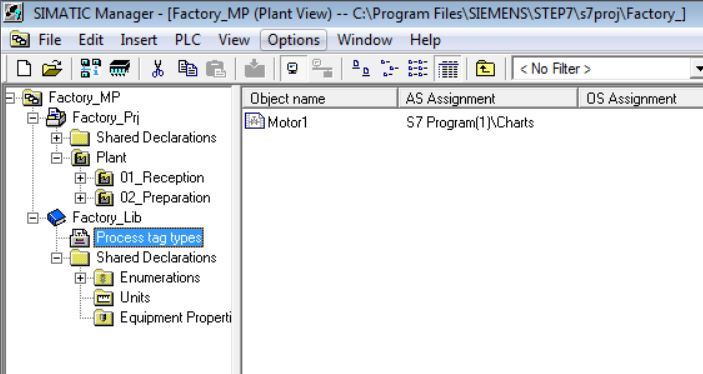
• Create Motor1 CFC in the Plant folder. Right-click on the Plant object and select Insert New Object > CFC menu item.
• Right-click on the Motor1 object and select Process Tags > Create/Change Process Tag Type... menu item

• In the Assistant window, click on the Next button. Factory_Lib library was selected.

• Click on Finish button.

• The Process tag types folder was created in the Master Data Library.
A similar procedure can be applied to have the Model folder. We will study in detail Process tag types and Models later.
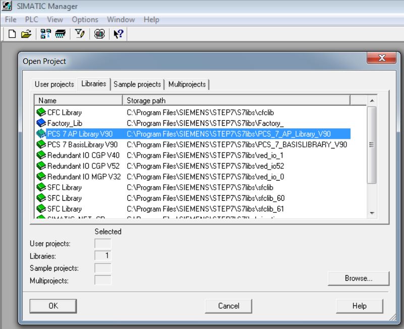
• Open APL 8.1 or 9.0 (SIMATIC Manager menu File > Open... menu). In the Libraries tab of the Open Project window select PCS 7 AP Library V81/V90.
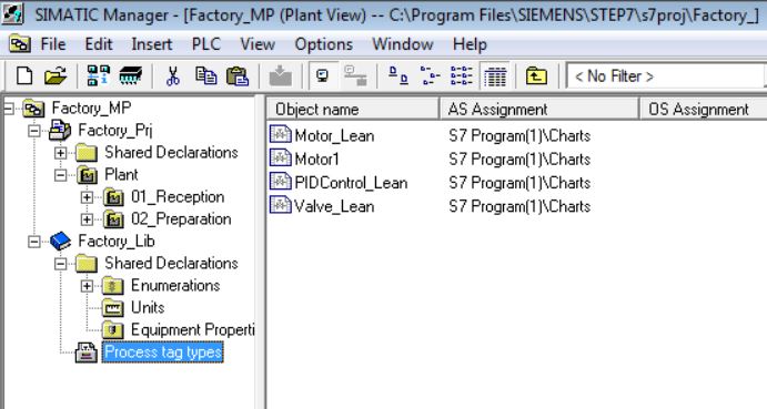
• Copy Valve_Lean, Motor_Lean and PIDControl_Lean templates to Master Data Library. In APL's Component View, the Templates folder, select Valve_Lean, Motor_Lean, and PIDControl_Lean and copy them (Ctrl + C). Keep the Ctrl key pressed when selecting more than one item to copy.

• Open Plant View of the Crushing Soybean project in the Process Tag Types folder of the Master Data Library (Factory_Lib) and paste the templates (Ctrl + V).
• Delete Motor1 CFC from the Plant folder. Right-click on the Motor1 object and select Delete menu item.

• Click on Yes to confirm.
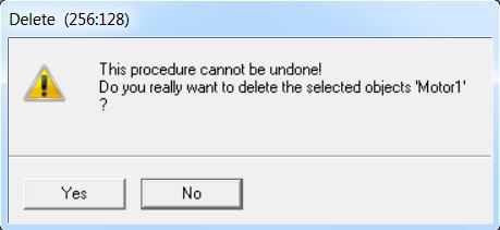
• Delete Motor1 Process tag type from the Process tag type folder of the Master Data Library. Right-click on the Motor1 object and select Delete menu item.

• Click on Yes to confirm.
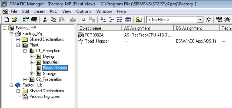
• Copy Motor_Lean from Factory_Lib Master Data Library to 01_Reception\Road_Hopper.

• Rename to TCR0802A.
• Connect Motor.Start parameter with FbkRun.SimPV_In. This interconnection is made in the motor cfc to simulate the running motor return signal. First click on the Motor.Start parameter and then click on the FbkRun.SimPV_In parameter.

• FbkRun.Sim_On = 1. Enable block simulation. Double-click on the FbkRun.Sim_On parameter and set the Sim_On parameter with value 1 (true).

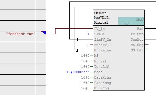
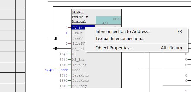
• Make field interconnections. FbkRun.PV_In interconnected with TCR0802A_YS (digital input). Primeiro, apague a conexão existente com o texto "feedback run" (Delete Interconnections menu item). To make an interconnection to address, right-click on the parameter and select Interconnection to Address...

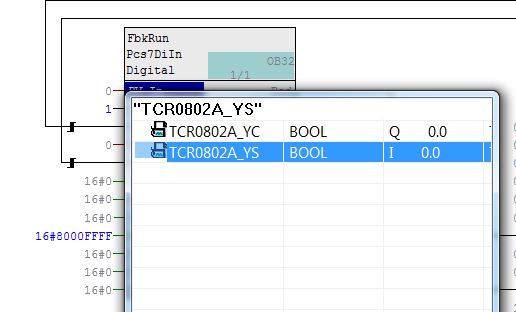
• Interconnection made with TCR0802A_YS digital input.

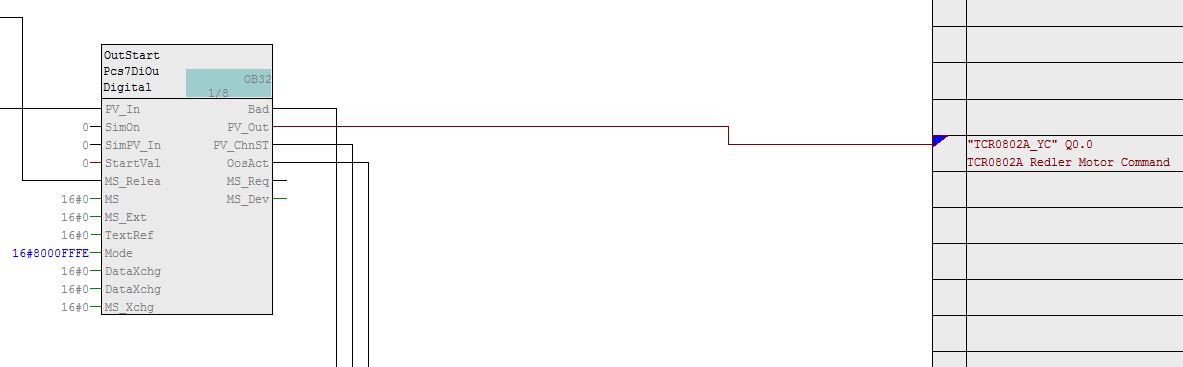
• Make field interconnections. OutStart.PV_Out interconnected with TCR0802A_YC (digital output). First, delete the existing connection with the "output start" text (Delete Interconnections menu item). To make an interconnection to address, right-click on the parameter and select Interconnection to Address...
Watch on Youtube
Channel Blocks
Various types of channel blocks are provided in the library of PCS 7 for the processing of input and output signals. Channel Blocks are ready blocks (FBs) that handle system I/O signals.
The "Generate module drivers" function interconnects and configures the required I/Os automatically within the CFCs. The function is called and executed if any hardware modification is detected when the program is compiled.
Standard channel blocks: Pcs7AnIn, Pcs7AnOu, Pcs7DiIn, Pcs7DiOu, Pcs7DiIT
FF/PA channel blocks: FbAnIn, FbAnOu, FbDiIn, FbDiOu
Compile and Download AS
An AS can be compiled and downloaded to a controller by various means:
1 – Through HW Config (Component View > AS > Hardware) to compile and unload the hardware configuration for the CPU.

 Compile button
 Save and Compile button
 Download button
2 – Through NetPro (Component View > Menu Options > Configure Network) to compile and unload the configuration of networks and connections.

3 – Through CFC and SFC.
4 – Through SIMATIC Manager to compile and download individually in a multiproject.
Crushing Soybean Project
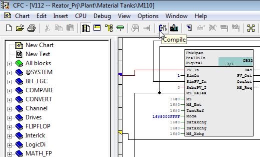
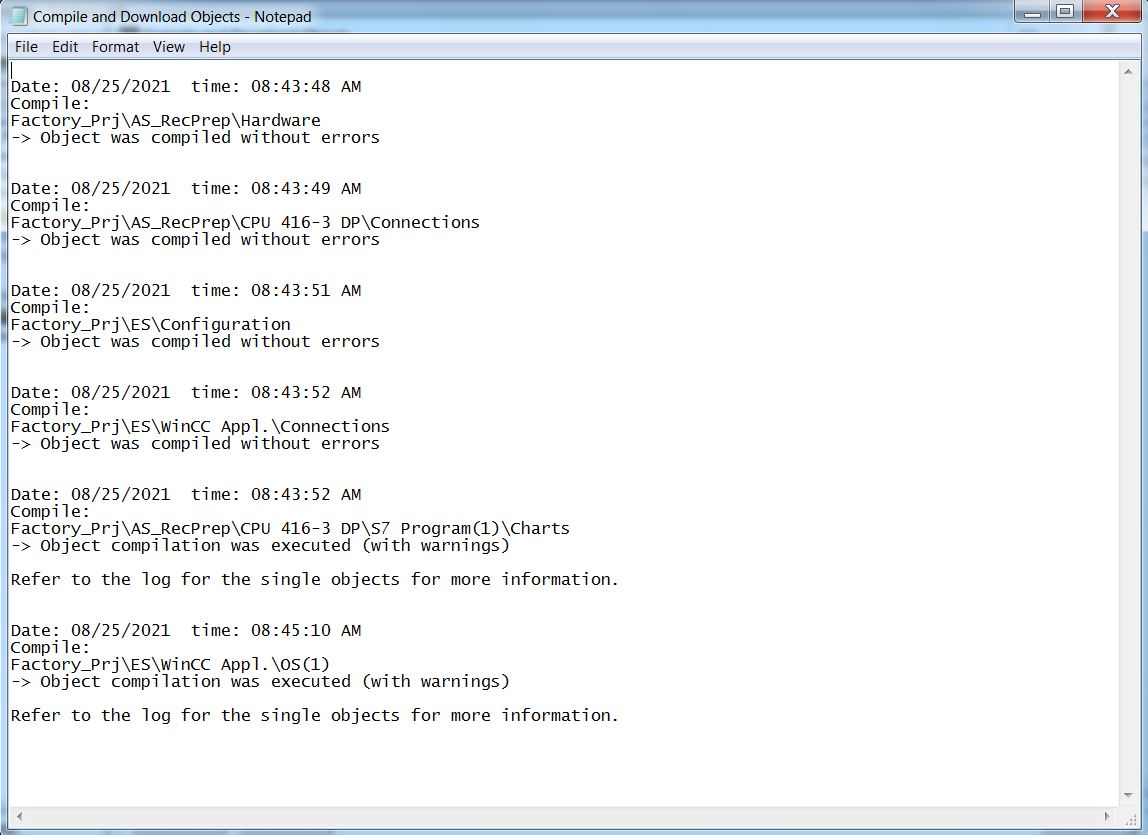
• Compile AS. Right-click on Factory_Prj and select PLC > Compile and Download Objects. Select Compile Only option. Click on Start.
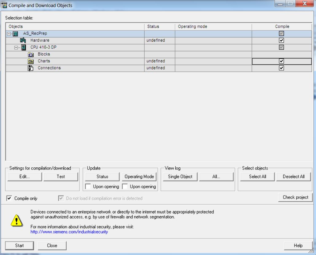
• Click on Yes to confirm.

• Compilation Log (without errors).
Simulation
• Open PLCSim (Windows Explorer > All programs > Siemens Automation > Options & Tools > S7-PLCSIM Simulating Modules).

• Download AS to PLCSim. In SIMATIC Manager Component View, right-click on AS_RecPrep and choose PLC > Download. It is not recommended to use the Compile and Download Objects... option with PLCSim.

• Click on Yes to confirm.

• Change CPU mode in PLCSim to RUN-P (running and released for programming).

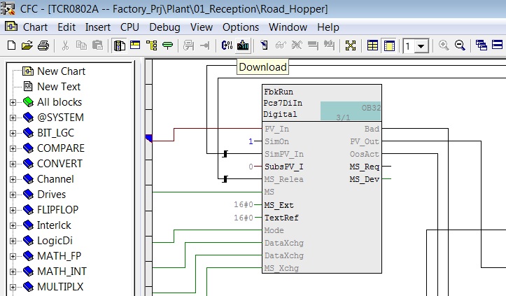
• Open TCR0802A CFC. Download to the simulator. Click on the Download button.
• Select option to download the entire program. The CPU will go into Stop mode before downloading. Click OK.
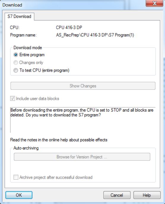
• Confirm CPU stop and download. Click on Yes.

• Restart CPU.

• Set Test Mode ON.

Watch on Youtube
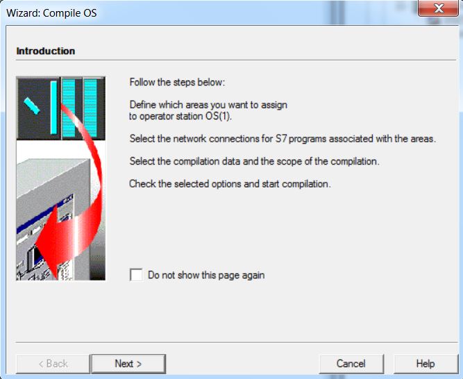
• Compile OS. Right-click on the WinCC OS(1) project and select the Compile menu item.

• Click Next in the introduction window.
• Assignment of areas to Operator Stations. Click Next.

• Select TCP/IP network connection for simulation. Click the Connection button.

• Select Plantbus - TCP/IP. Click on Next.

• Select the data you want to compile and the scope of the compilation. Click on Next.

• After the first compilation, the window appears with options to compile Tags and messages, in addition to the scope Entire OS (complete compilation, with or without memory reset) and Changes (only new changes).
• Click on Compile button.

• Option to view the compilation log.

Watch on Youtube
• Open WinCC Explorer. Right-click on OS(1) and select Open Object menu item.
OS Project Editor - Layout

Avaliable Layouts – project screen resolution options.
Current Layout – selected screen resolution.
Monitor configuration – number and arrangement of monitors.
Overview extended configuration – Detail... The overview area, at the top of the screens, contains a number of buttons representing the areas of the plant. By default, 16 buttons are displayed. Button adjustments are made in the Overview extended configuration.

Number of Areas: determines the reserved number of buttons for the areas in the overview.
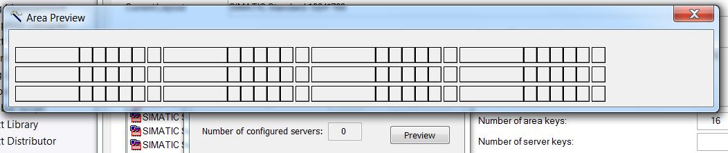
Horizontal = 4 and Vertical = 4. Preview:

Horizontal = 2 and Vertical = 3. Preview:

Crushing Soybean Project
• Open OS Project Editor.

• Click on Detail button of Overview extended configuration. Change the number of areas in the Factory_Prj project to Horizontal = 4 and Vertical = 3.

• Click on Preview button. Click on OK or Apply of OS Project Editor. Close OS Project Editor.
Area
In the Area tab of the OS Project Editor, it is possible to sort the areas in the overview and insert empty buttons.
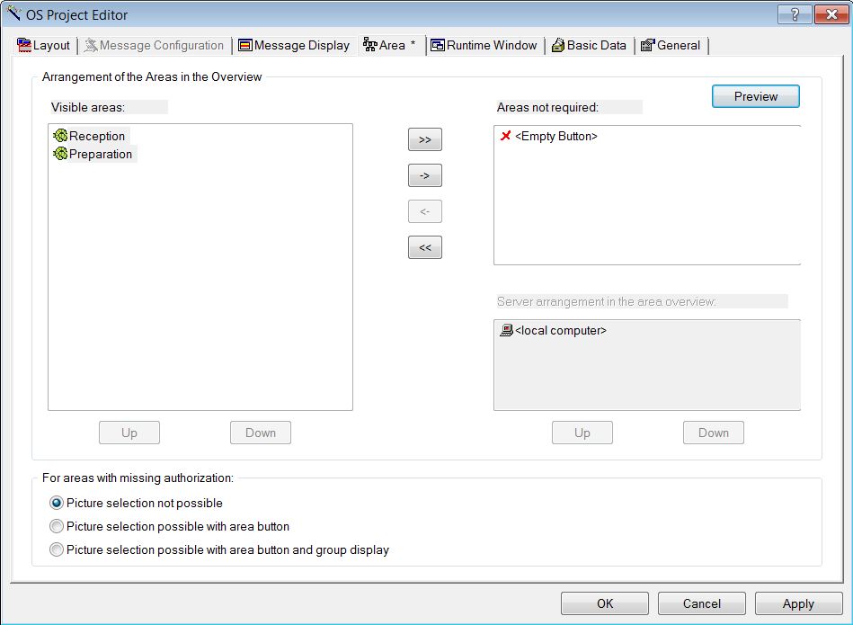
Clicking the Preview button:

Picture Tree Manager
In accordance with your plant configuration, pictures are inserted in the plant hierarchy to show the process to the operator of the plant. You can enter a picture by hierarchy folder. Inserting pictures into the plant hierarchy results in a picture hierarchy which serves as an important aspect when managing process screens. When compiling the OS, Picture Tree Manager has the hierarchy of the plant hierarchy.
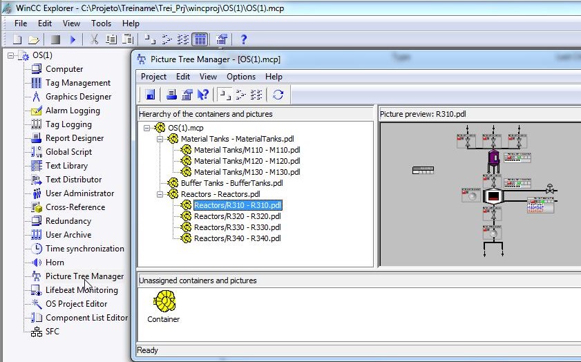
The hierarchy in Picture Tree Manager consists of containers and pictures. Containers are groupings of pictures.
Control and Monitoring Attributes
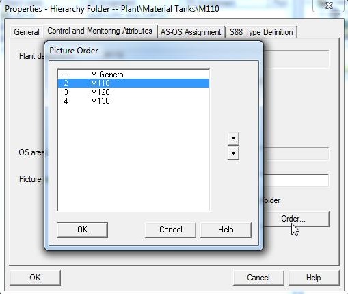
To open Control and Monitoring Attributes from a hierarchy folder in the Plant View of SIMATIC Manager, open the properties of the desired folder in the Control and Monitoring Attibutes tab (ex. Plant\Material Tanks\M110 > Object Properties).
The name of a picture in OS can be different from its name in the plant hierarchy by changing the Picture name for OS property.

The order of pictures in an OS area can be changed by clicking the Order... button
Crushing Soybean Project
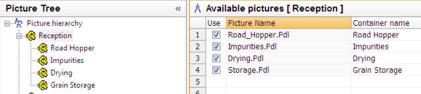
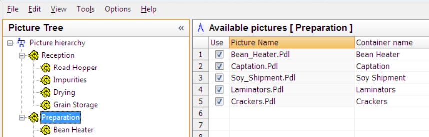
• Open Picture Tree Manager.
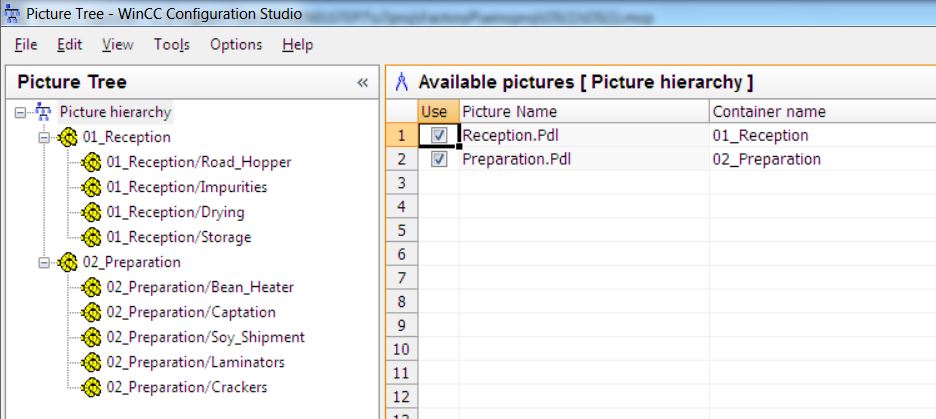
• Change Containers name as indicated in the images.

Note: If in a next OS compilation we select the option to compile Picture Tree, the changes made in Picture Tree will be lost (in this case the Container Name values were changed).
• Open Wincc Explorer and Tag Management.

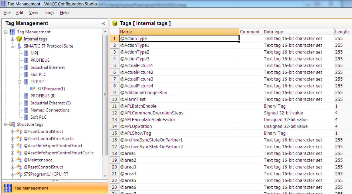
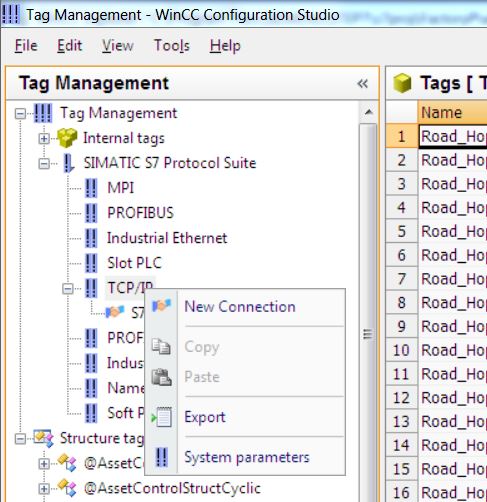
• Change Logical device name of TCP/IP protocol in Simatic S7 Protocol Suite. Right-click on TCP/IP and select menu item System Parameters. Select Unit tab and change Logical device name to PLCSim (TCP/IP). Close Tag Management.

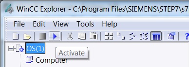
• Run WinCC project and start TCR0802A motor. In WinCC Explorer, select File > Activate. Navigate to picture Road_Hopper (submenu in the Reception menu) to display TCR0802A.
Attention - in some versions of PCS7 there is a problem with description on some faceplates, such as valve and motor. To resolve the issue, follow the steps:
1 - At WinCC Explorer, open Text Library.
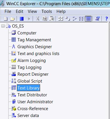
2 - Select lines 1 to 10.
3 - Right-click and select Delete menu item.
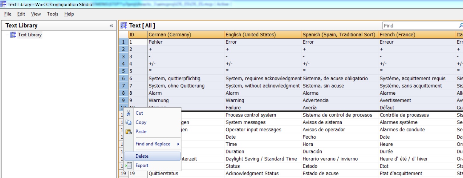
4 - Close Text Library.
Watch on Youtube
Generating block icons
Block icons are used for operator control and monitoring of plants or units in process mode. The block icons are required for block instances, which can be controlled and monitored, from the CFCs.
You can specify whether to create block icons for each of the process pictures on the PCS 7 OS and whether to store them in this process picture.
You can define the following settings in the plant view or in the process object view before compiling the OS:
• Select the "Derive block icons from the plant hierarchy" option for each process picture.
• If you select a "Multiproject", "Project" or "Hierarchy folder" object and then execute the "Create/Update Block Icons" function, the block icons are automatically inserted into the process pictures in accordance with the plant hierarchy and linked to the corresponding process tag.
Generating units and operator texts
Faceplates, which display the following block information, are used to display the process to the operator in process mode.
• Measured values
• Operating limits
• Units
• Operator texts
These texts are already included in the block types you use for a CFC. The unit and operator texts are only displayed in the language that is stored for the block types, irrespective of the current language selection.
The unit and operator texts for block types from the supplied libraries (for example PCS 7 Advanced Process Library) are only available in English.
You can change unit and operator texts (e.g. translate them into a different language) in the CFC in the properties for the block type or block instance.
Unregistered user. Buy the training at jats.com.br.