PC Station configuration
Shared Declarations
If you have created your multiproject with the PCS 7 wizards, the master data library already contains a "Shared Declarations" folder. You can then use this to store shared declarations that can be used by various applications. You can explicitly create the "Shared Declarations" folder if it does not yet exist.
The "Shared Declarations" folder contains the following subfolders:
• Enumerations
• Units
• Equipment properties
You can define the following elements as shared declarations:
• Enumerations
You can use enumerations to define textual representatives for the parameter values of the block or chart I/Os with data types "BOOL," "BYTE," "INT," "DINT," "WORD," and "DWORD". A suitable text is assigned to each value of an enumeration and this is displayed at the I/O. Several values can be assigned to each enumeration.
• Units
The unit of measure (for example, mbar, l/h, kg) is text with a maximum of 16 characters. It can be entered during the parameter and interconnection descriptions of block or chart I/Os. It is used for example, in process pictures when visualizing the values of the block I/Os. All the units of measure included in the CFC basic set are available as defaults.
• Equipment properties
Equipment properties are parameters of a unit, such as shell material, volumes etc. The type of equipment property is defined as a "shared declaration". Instances of this type are used in SIMATIC BATCH and its attributes are individually adapted.
Crushing Soy Project
• Insert Shared Declarations for the Factory_Prj project. Select project, right-click and select Insert New Object > Shared Declarations.

Master Data Library
When creating CFC charts, you should work with the master data library. DO NOT copy any blocks and process tag types directly from PCS 7 standard library to your project's CFC chart. Create the blocks and process tag types in the master data library and copy them from that library to the CFCs charts.
Below, the master data library Training_Lib (blue book) contains in the Blocks folder several FBs from the APL v8.1 library (Component View image).

Below are the Process tag types valves, motors, PIDs, etc.) from the APL v8.1 library: Motor_Lean, PIDControl_Lean and Valve_Lean.
Note: Process tag type will be studied in detail later in the course.

What are the advantages of the master data library?
The use of the master data library ensures that the same block version is used in the project, avoiding confusion. This is especially important if more than one engineer is working on a multiproject.
The use of the master data library also provides another convenient PCS 7 function: hide libraries. This function allows you to hide all libraries except the master data library.
The master data library is archived automatically when multiproject backup.
How to store objects in the Master Data Library
Changes in the blocks
You can change the block properties on the master data library. For example, you can tailor specific messages to the requirements of your project. Each instance of the block you created in CFCs will have its properties changed automatically. With this, you have to change the block only in the master data library and not repeatedly for each created instance of the block.
Modifications of a block intentionally to a specific CFC are made directly in the block instance in that CFC. This includes, for example, input and output parameters, such as setpoints and limit values.
Master Data Library and process tag types
You can also store process tag types provided by PCS 7 in the master data library. All blocks included in the process tag type are automatically included in the Blocks folder of the master data library.
Watch on Youtube
Crushing Soy Project
• Insert a Master Data Library Factory_Lib to the Factory_MP multiproject. In SIMATIC Manager, select File > New... menu item.
• Select Libraries tab.
• Insert Name = Factory_Lib. Type = Library. Choose storage location (default C:\Programs Files (x86)\SIEMENS\STEP7\s7libs). Select Add to current multiproject (Factory_MP) to include the library in the Factory_MP multiproject.


• Close the Factory_Lib library window and work within the Factory_MP multiproject.
• In Component View, enter S7 Program for Factory_Lib. Right-click on the Factory_Lib object and select Insert New Object > S7 Program menu item.

• Insert the Charts folder into the S7 Program of Factory_Lib. Right-click on the S7 Program object and select Insert New Object > Chart Folder menu item.

• Set Factory_Lib library as Master Data Library. When including the library in the multiproject, it is inserted as a common library. To make it the Master Data Library for the multi-project, right-click on the Factory_Lib library and select Multiproject > Define as Master Data Library menu item.

• The color of the book icon changes from green to blue, indicating the Master Data Library.
• Select Plant View. Add Shared Declarations folder to Master Data Library. Right-click on the Factory_Lib object and select Insert New Object > Shared Declarations menu item.

Watch on Youtube
PC Station configuration
• The computer or virtual machine must have changed its name to ES, if this has not been done before installing SIMATIC PCS 7 (guidance given in the installation). Open the Control Panel - System and Security - System. Click Change settings and change the computer name to ES. Restart the computer or the virtual machine after the change.
• Change fixed IP from computer or machine to 192.168.0.2 (Mask 255.255.255.0).

• Add Simatic PC Station to Factory_Prj multiproject. Right-click on Factory_Prj object and select Insert New Object > SIMATIC PC Station.

• Rename the PC Station to ES.

Note: The name of the station (PC station) in the project must be the same as the physical machine. The name ES is a random
name (the initials of Engineer System - default name in PCS 7 for the configuration machine).
You may use any name. The important thing is that the name in the project is the same as the name of the physical machine.
When the project and the machine have the same name, the PC Station icon will have a yellow arrow
 .
.

Note: it is possible that the yellow arrow does not appear, even with the correct configuration.
• Select PC Station ES object and open Configuration.

• Insert Ethernet communication target for ES (IE General). It is in the catalog at Simatic PC Station\CP-Industrial Ethernet\IE-General SW V8.1. Add in position 1 of the PC Rack (index 1).
• IE General of ES with IP Address 192.168.0.2 and mask 255.255.255.0.
• Select PlantBus subnet.


• Insert WinCC Appl. on PC Index 2 - Select from catalog the SIMATIC PC Station\HMI\WinCC Appl. and drag to Index 2 from the PC rack. Save and compile HW Config. The compilation may take a few minutes. Close HW Config.


Watch on Youtube
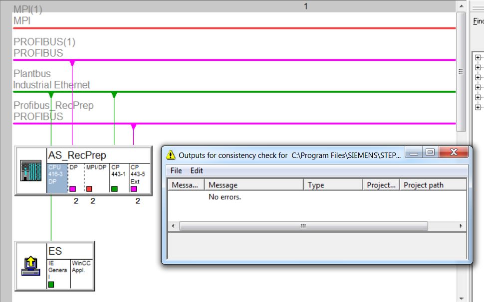
NetPro (Configuration Network)
In the NetPro application the networks and connections are configured. Using NetPro, you can configure, do parameter assignment, and document the network configuration of your plant in a simple and clear way. The NetPro opens in the SIMATIC Manager Options menu > Configure Network.

Crushing Soy Project
• Open NetPro. Select Options > Configure Network menu item.

• Right-click on CPU416-3 of AS_RecPrep and select Insert New Connection.

• Choose WinCC Appl of ES. Choose connection type S7 Connection. Click OK.

• Click OK.

• Save and Compile.

• Select Compile change only and click on OK.

• Observe the color change of the AS_RecPrep and ES objects from orange to white after successful compilation.
PC Station Configure (PLC Configure)
The PLC Configure function of the PCS7 provides a comfortable configuration of PC stations. The configuration is done in the project and downloaded to the station (computer).
The function is activated by right-clicking on the PC Station (ES) and choosing PLC menu item > Configure ...

The Configure window opens. In it will be chosen the station receive the PC Station configuration (Configure option). It is also configuration of a PC Station (Display option)
• Acessible computers: displays the network stations.
• Use configured computer name: disable this option if you want to select a new station to transfer or view the configuration.
• Target computer: station/target selected for the transfer or display of the configuration (chosen from Accessible computers).
• Configure button: Download the PC Station configuration selected from the project to station/target.
• Display button: opens the "Configuration target computer "whose current configuration is shown with its modules and applications.
Crushing Soy Project
• Open PLC Configure. Right-click on the PC Station ES and select the PLC menu item > Configure...
• Uncheck Use configured computer name. Click on the Configure button.

• A message will appear indicating with the possible configuration. Click OK.

• A station reconfiguration message will appear. Click OK.

Transfer successful.

• Click on Display button.

• In the Configure window, click Close.
• Open Station Configurator Editor (All Programs > Siemens Automation menu or Windows taskbar).


Download the network connections to the ES station.
• Select Factory_Prj and open NetPro (menu Options > Configure Network).
• Select PC Station ES.
• Click the Download button  for
download network configuration (connections) to the station. Click on Yes.
for
download network configuration (connections) to the station. Click on Yes.

• Stop modules to download. Click on Ok.

In Station Configuration Editor the Conn column shows the downloaded configuration (highlighted in red in the image below).

Watch on Youtube
Next
Unregistered user. Buy the training at jats.com.br.