Visualizing the Process
Ladder Programming Language (LAD)
LAD is a graphic language. Its representation is based on circuit diagrams. The program is developed in one or more networks. A network contains a force lane on the left side. The binary signals are arranged in the form of contact in the networks. A serial arrangement of the elements in a network creates a serial connection; the arrangements in simultaneous branches create a connection in parallel. Complex functions are represented in boxes.
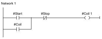
Network LAD example
The image below shows a LAD network with two contacts normally open, a normally closed contact and a coil.
LAD elements
A LAD program consists of separate elements that are arranged in series or parallel on the network's power rail. Most program elements should receive tags.
The structure of a ladder diagram corresponds to a series of relay switches.
The left power rail is on the left in the LD editor. It corresponds to the phase (L ladder) of a ligation. In the LD account, as well as in electrical connections, only the LD objects that are connected to the power supply are processed. The right rail (right power rail) corresponds to the neutral wire. All coils connect directly or indirectly to this lane, creating a current flow.
Network LAD elements

1 – Power rail
Each LAD network consists of a power rail that contains at least one rung. A network can be extended with the addition of new rungs. Branchs are used to parallel programming in the rungs.
2 – Rung
3 – Branch
4 – Contact
Contacts are used to create or interrupt a connection for the flow of current between two elements. The current continues from the left to the right. The contacts can be used to extract the status of the signal or the value of an operand and control it depending on the result of the current flow.
The following types of contacts are allowed in an LAD program:
• Normally open contact
Normally open contacts pass the current if the status of the signal of the specific binary operand is "1".
• Normally closed contact
Normally open contacts switch to the current if the signal state of the specific binary operand is "0".
• Contact with additional function
Contacts with additional function go to the current if a it is addressed specifically. With these contacts it is possible to perform an additional function, such as a comparison.
5 – Coil
Coils are used in binary control operands. Coils they can define a set or reset for a binary operand depending on the state of the signal of the result of the logic of the operation. The following types of coils are allowed in a LAD program:
• Standard coils:
Standard coils set a binary operator if there is flow of current in the coil. The "Assignment" instruction is an example of a standard coil.
• Coils with additional function
These coils have additional functions added in the evaluation of the result of the logic of the transition. The control program is an example of a coil with additional function.
6 – Box
Boxes are elements with complex functions. An Empty box must be inserted and then assign a task to it. The following types of boxes are allowed in a LAD program:
• Boxes without the EN/ENO mechanism
The box is executed depending on the state of the signal of the inputs from a box. The status error can not be consulted.
• Boxes with EN/ENO mechanism
The box is only executed if the enable input "EN" loads the signal status in "1". If the box is processed correctly, the enable output "ENO" has the signal status in "1". If an error occurs during processing, the "ENO" has a reset (set to "0").
Project 1
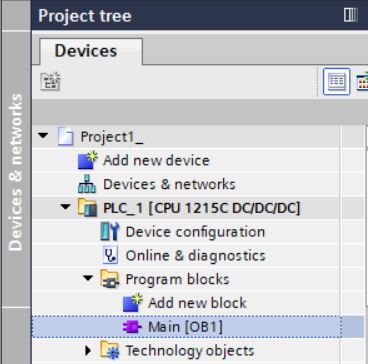
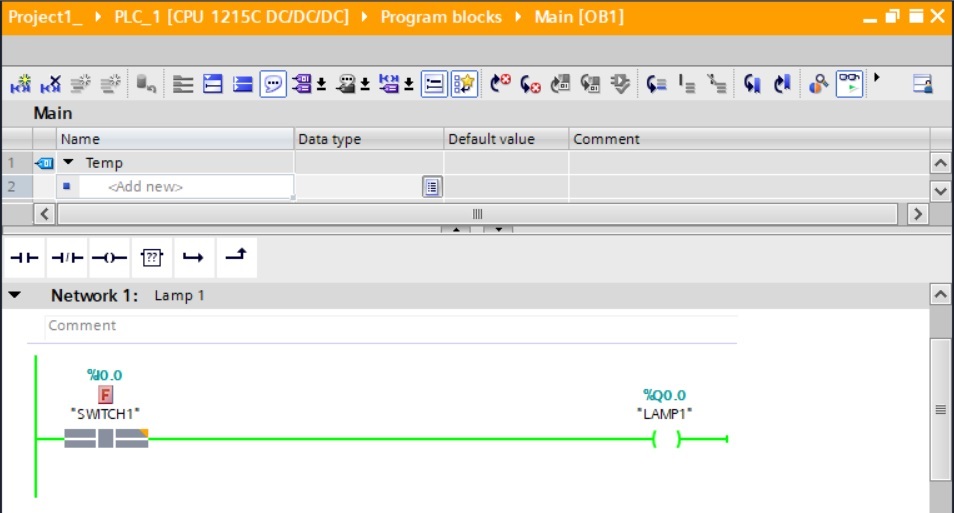
• Open the Main block [OB1] for editing the logic. Double-click on the Main block in the Project tree. This block is automatically generated by the system.
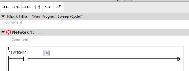
Network 1
Through this network, switch 1 will control lamp 1. When the switch is in the Off position (input with logic level 0 or 0 VDC), the lamp will turn off (output with logic level 0 or 0 VDC). When the switch is in the On position (input with logic level 1 or 24 VDC), the lamp will light up (output with logic level 1 or 24 VDC). We will use a normally open contact and a coil in the network.
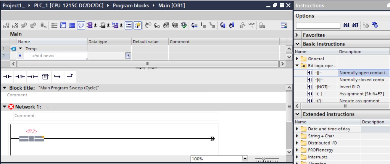
• Insert a normally open contact into network 1. Select the Normally open contact instruction under Basic Instructions > Bit logic operations. Drag to network 1.
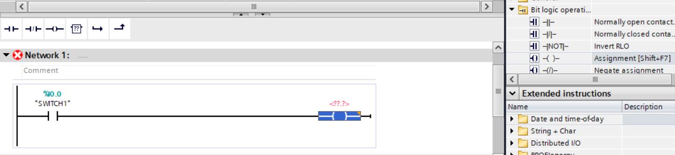
• Select the first digital input SWITCH1 for the normally open contact.
• Insert a coil into network 1. Select the Assignment instruction (coil) in Basic Instructions > Bit logic operations. Drag to network 1.
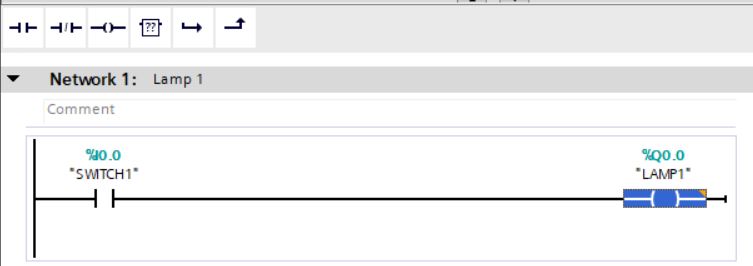
• Select the first LAMP1 digital output for the coil.
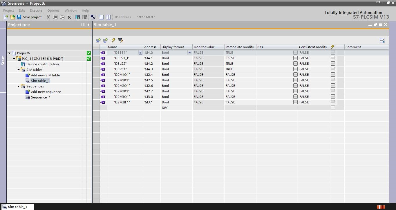
S7_PLCSIM
PLCSIM allows you to find errors in the project without having to connect to a real PLC.
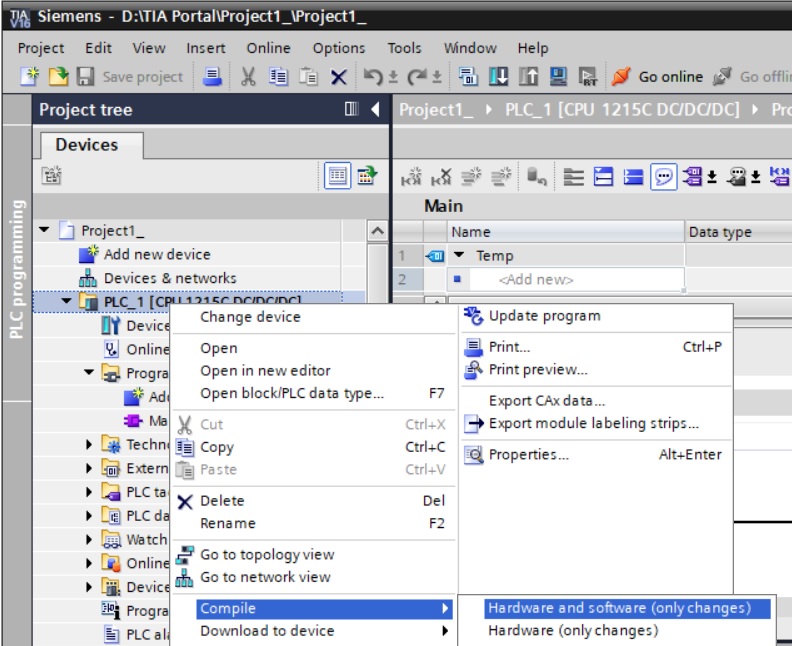
• Compile PLC_1. Right-click on PLC_1 and select menu item Compile > Hardware and software (only changes).
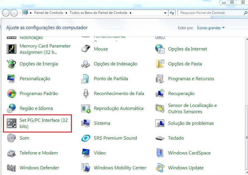
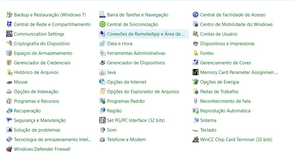
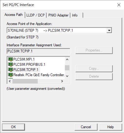
• Configure Set PG/PC Interface to PLCSIM.TCPIP. Set PG/PC Interface is in the Windows Control Panel.
Windows 7
Windows 10
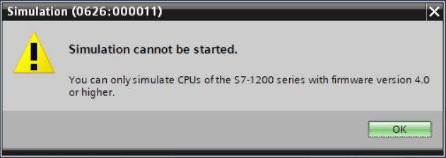
• Simulate project 1. Select device PLC_1, right-click and select Start simulation menu item.

• Simulation on S7-PLCSIM version 16 cannot be started because S7-1200 series CPUs only allow simulation with firmware version 4.0 or higher. The current controller version of the controller is version 3.0. Click on OK button.
If the simulation is allowed in the version in which you installed TIA Portal and S7-PLCSim, proceed without changing the firmware.
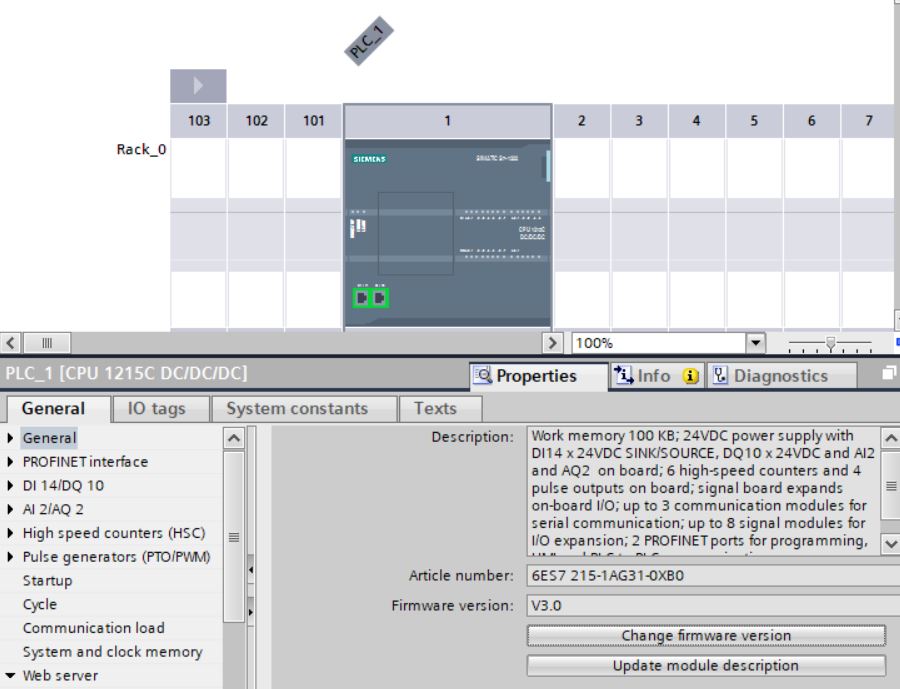
• In Device view, select the controller properties and click on the Change firmware version button.
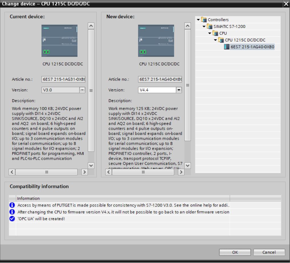
• Switch to v4.4 version. Click on OK button.
• Compile hardware and software from PLC_1.
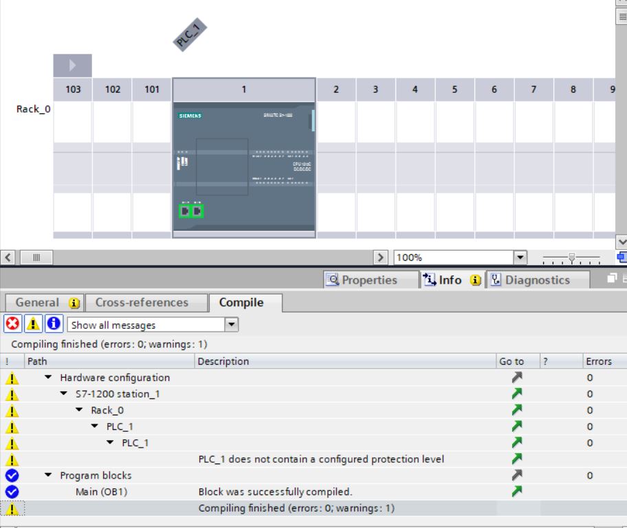
A warning message was generated on compilation, as there is no protection level configured for the controller. The controller will run normally as no errors were generated.
• Simulate project 1. Select device PLC_1 again, right-click and select Start simulation menu item.
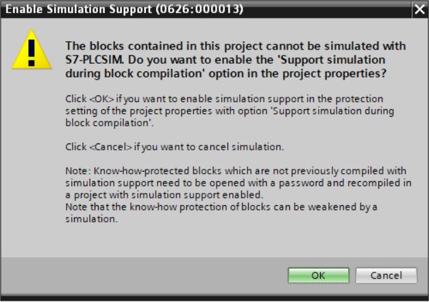
• Enable simulation support. Click on OK button.
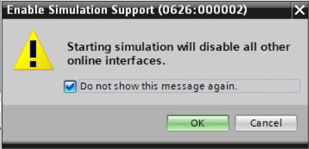
• The simulation will disable all other online interfaces. Click on OK button.
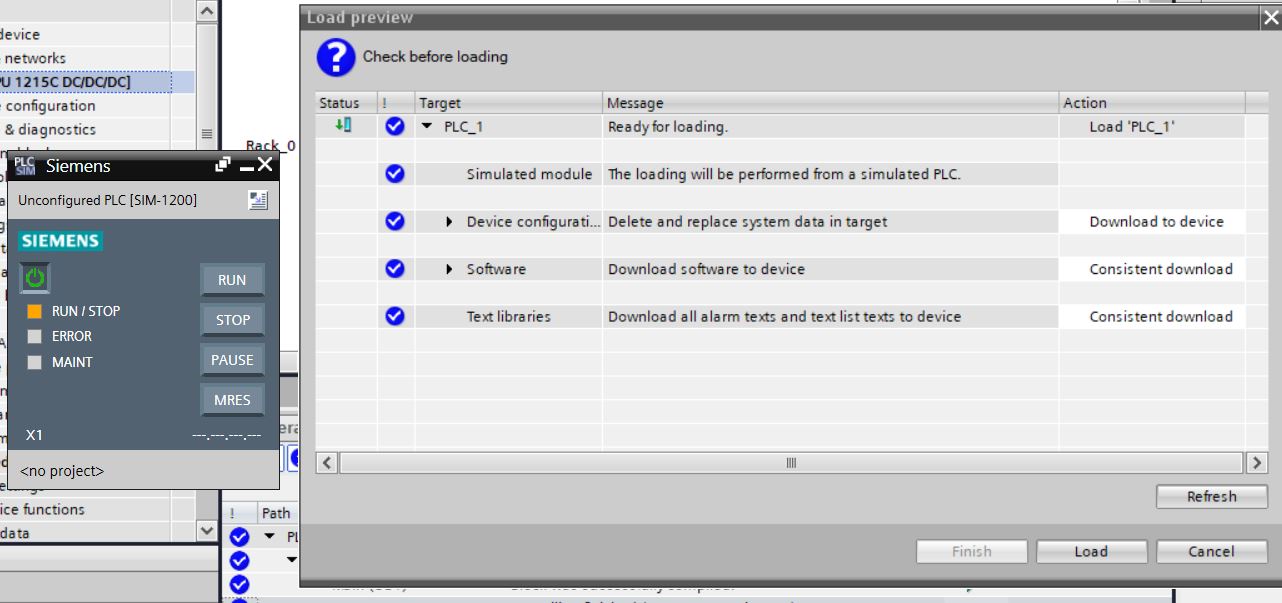
• Download program from PLC_1 to S7-PLCSIM. Click Load.
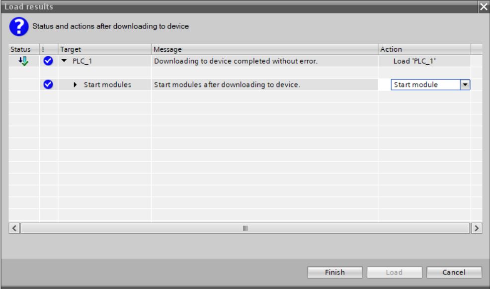
• Select Start module and click the Finish button.
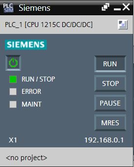
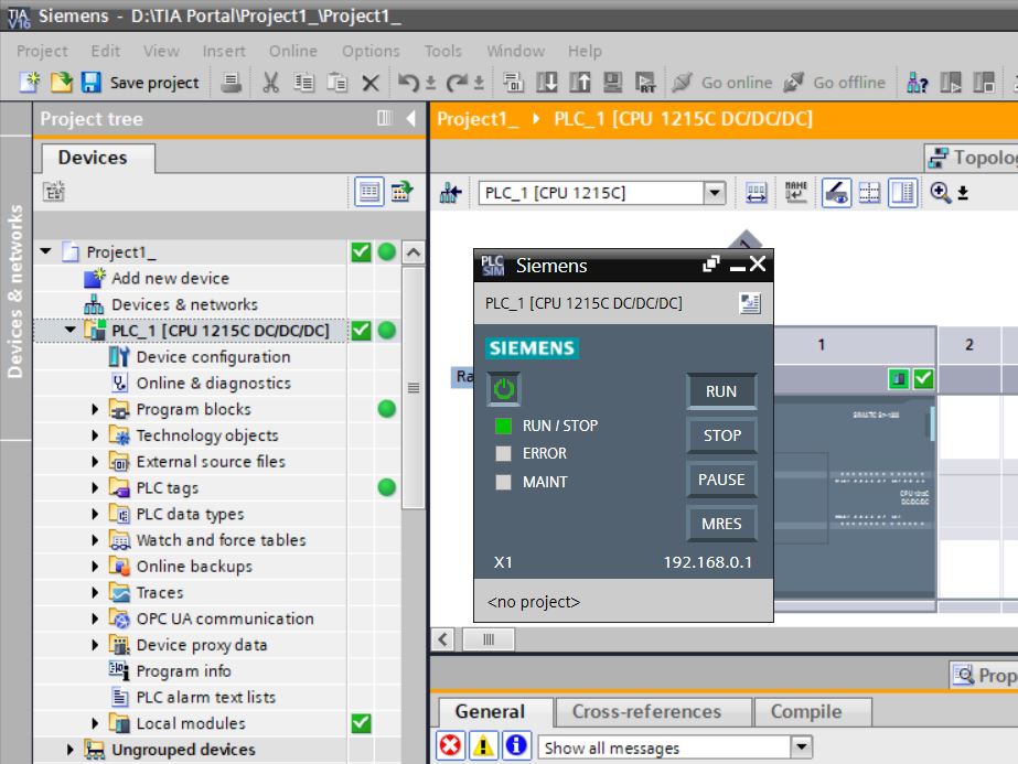
• View S7-PLCSIM window.
• Right-click on PLC_1 and select the Go online menu item.
• Note on network 1 that the SWITCH1 contact starts with logic level 0 (0 VDC) and the LAMP1 coil is de-energized. Digital output Q0.0 is at logic level 0 (0 VDC) and lamp 1 is off.
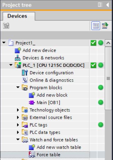
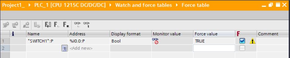
• Open Force table in Watch and force tables (double-click).
• On line 1, enter address %I0.0 to force SWITCH1 digital input.
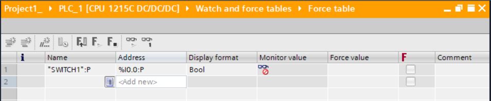
• In the Force value column, enter the TRUE value.
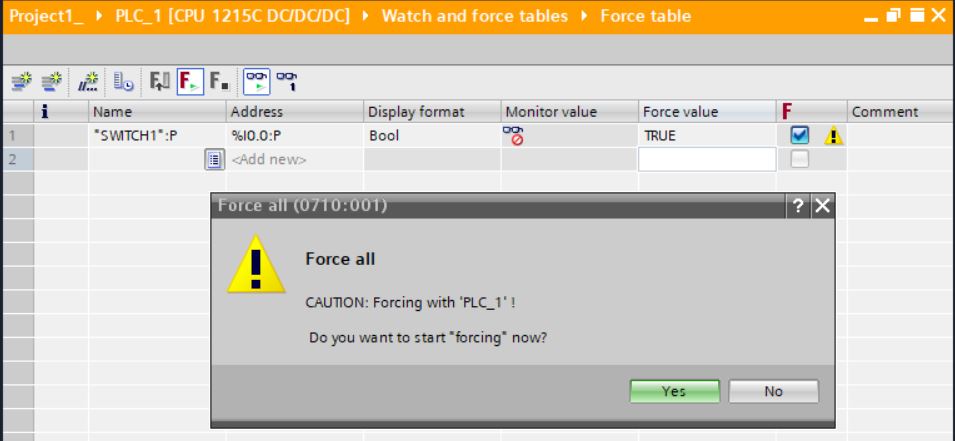
• Click on the button Start or replace forcing... (sixth button of the Force table). Click on the Yes button.
• Note on network 1 that the SWITCH1 contact has closed and the LAMP1 coil has been energized. Digital output Q0.0 goes to logic level 1 (24 VDC) and lamp 1 lights up.
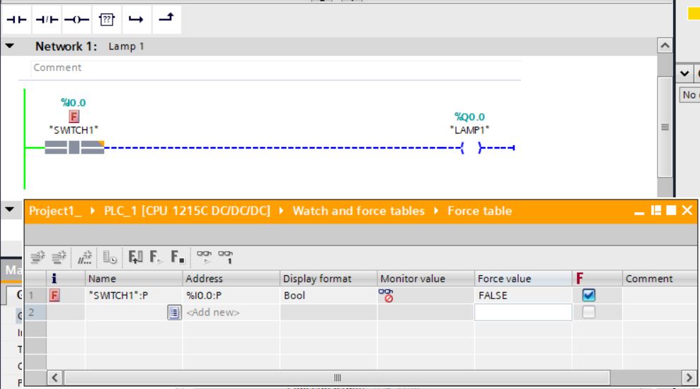
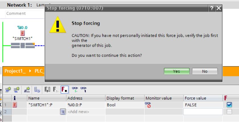
• In the Force value column, enter the FALSE value.
• Click on the button Start or replace forcing... (sixth button of the Force table). Click on the Yes button.
• Note on network 1 that the SWITCH1 contact has been opened and the LAMP1 coil has been de-energized. Digital output Q0.0 goes to logic level 0 (0 VDC) and lamp 1 goes out.
• Click on the Stop forcing button (seventh button of the Force table). Click on the Yes button.
• Right-click on PLC_1 and select menu item Go offline. In offline mode, the controller remains running as it is in Run mode. Only project monitoring is terminated.
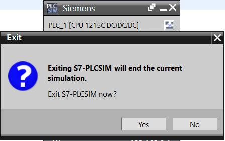
• Close the S7-PLCSIM window.
Normally Closed Contact
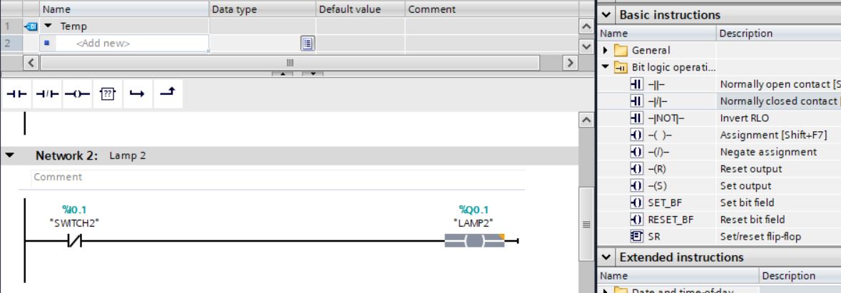
Network 2
Through this network, switch 2 will control lamp 2. When the switch is in the Off position (input with logic level 0 or 0 VDC), the lamp will light up (output with logic level 1 or 24 VDC). When the switch is in the On position (input with logic level 1 or 24 VDC), the lamp will go out (output with logic level 0 or 0 VDC). We will use a normally closed contact and a coil in the network.
• Insert a normally closed contact into network 2. Select the Normally closed contact instruction under Basic Instructions > Bit logic operations. Drag to network 2.
• Select the first digital input (SWITCH2) for the normally closed contact.
• Insert a coil into network 2. Select the Assignment instruction (coil) in Basic Instructions > Bit logic operations. Drag to network 2.
• Select the first digital output (LAMP2) for the coil.
• Save project.
• Compile the software changes from PLC_1. Right-click on PLC_1 and select Compile > Software (only changes).
• Simulate project 1. Select device PLC_1 again, right-click and select Start simulation menu item.
• Download program from PLC_1 to S7-PLCSIM. Click Load.
• Right-click on PLC_1 and select the Go online menu item.
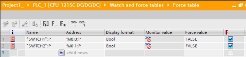
• Open Force table at Watch and force tables (double-click).
• Enter address %I0.1 to force SWITCH2 digital input.
• Open Default tag table at PLC tags.
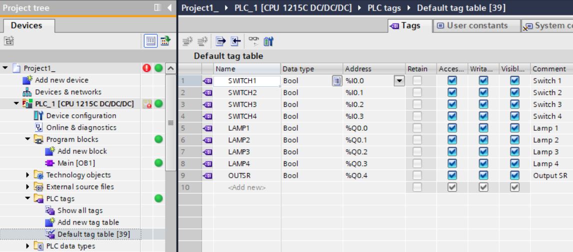
• Click the Monitor All button (fifth Default tag table button) to monitor the table tag values.
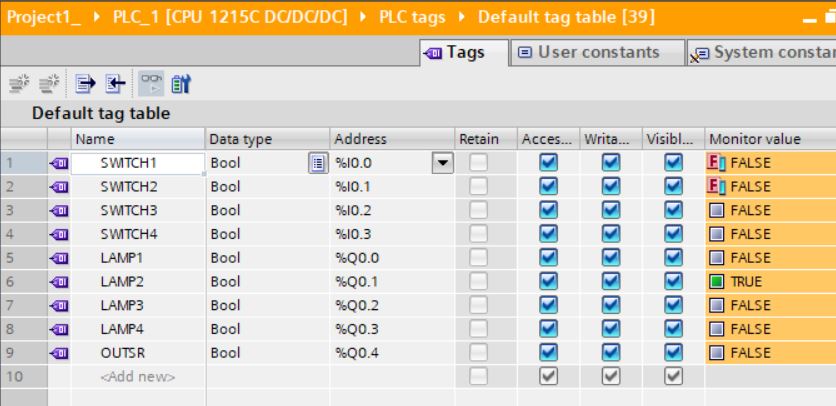
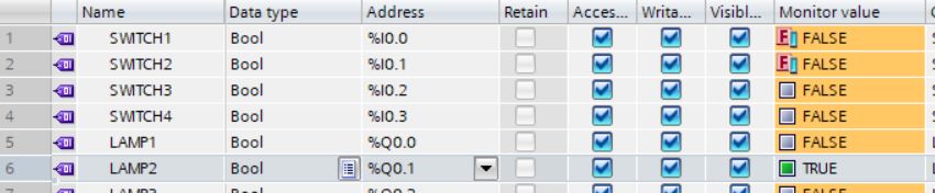
• Note on network 2 that the SWITCH2 contact starts with logic level 0 (0 VDC) and the LAMP2 coil is energized. Digital output Q0.1 is at logic level 1 (24 VDC) and lamp 2 is on.
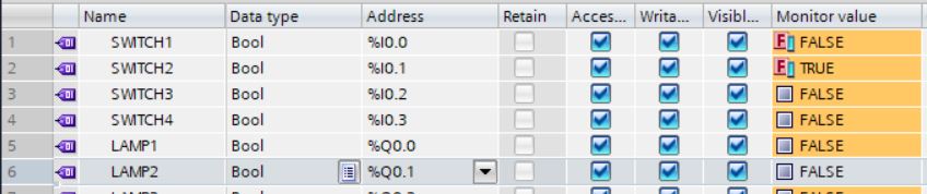
• In the Force value column, enter the TRUE value.
• Click on the button Start or replace forcing... (sixth button of the Force table). Click on the Yes button.
• Note on network 2 that the SWITCH2 contact has been opened (opens when energized) and the LAMP2 coil has been de-energized. Digital output Q0.1 goes to logic level 0 (0 VDC) and lamp 2 goes out.
• Click on the Stop forcing button (seventh button of the Force table). Click on the Yes button.
• Right-click on PLC_1 and select menu item Go offline.
AND - OR Logic
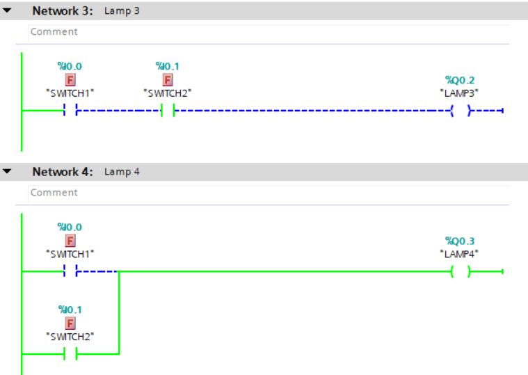
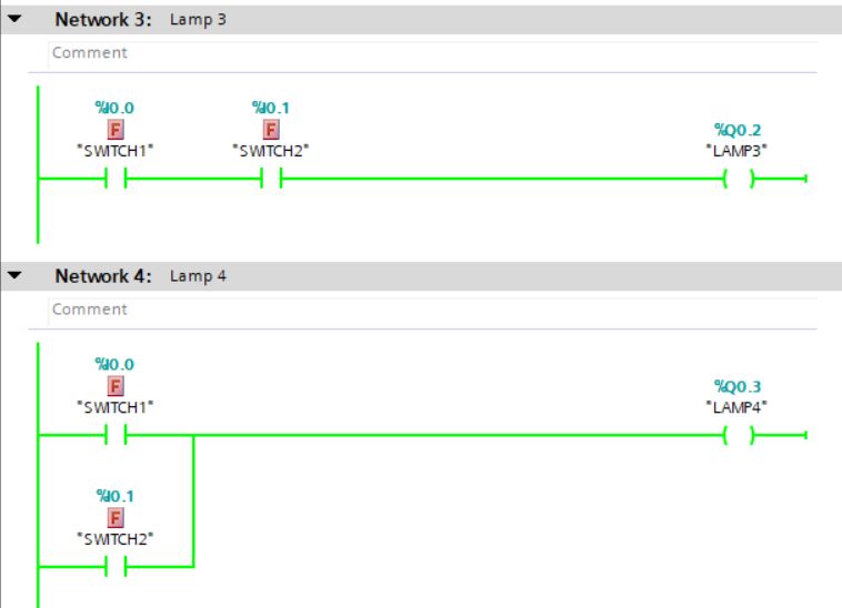
Network 3
• Insert SWITCH1 normally open switch in series with SWITCH2 normally open switch and triggering the LAMP3 lamp.
Network 4
• Insert SWITCH1 normally open switch in parallel with SWITCH2 normally open switch and triggering the LAMP4 lamp. Use Open Branch and Close Branch instructions for OR logic (parallel).

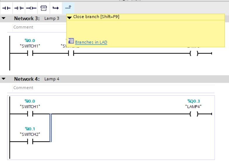

• Save the project and download it to the simulator. Test the changes by opening and closing the SWITCH1 and SWITCH2 switches and observing the status of the LAMP3 and LAMP4 lamps. As SWITCH1 and SWITCH2 are connected in series on network 3, the LAMP3 lamp only lights up when both switches are closed (logic level “1”). As SWITCH1 and SWITCH2 are connected in parallel on network 4, the LAMP4 lamp lights up when one of the switches is closed (logic level “1”) or when both switches are closed at the same time.
• Click on the Stop forcing button (seventh button of the Force table). Click on the Yes button.
• Right-click on PLC_1 and select Go offline menu item.
Set and Reset Instructions
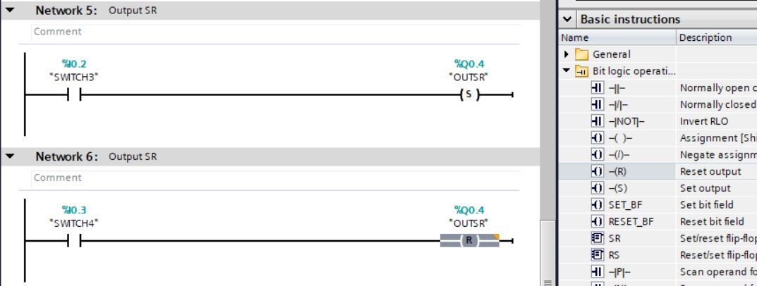
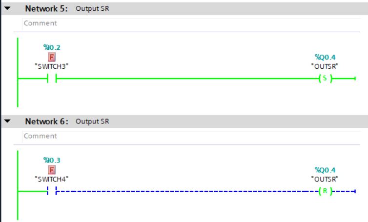
Network 5
• Insert normally open contact for SWITCH3. Insert Set output instruction located in Basic Instructions > Bit logic operations with OUTSR Output Set Reset tag.
Network 6
• Insert normally open contact for SWITCH4. Insert Reset output instruction located in Basic Instructions > Bit logic operations with OUTSR Output Set Reset tag.
• Simulate Set and Reset logic by alternating the values of the digital inputs and observing the result on the digital output.
• SWITCH3 and SWITCH4 can be non-retentive switches on a panel (pulsing buttons). SWITCH3 would be the push button to activate the equipment connected to the digital output OUTSR (24 VDC) and SWITCH4 would be the push button to deactivate the equipment connected to the digital output OUTSR (0 VDC).
• Click on the Stop forcing button (seventh button of the Force table). Click on the Yes button.
• Right-click on PLC_1 and select menu item Go offline.
Positive Edge
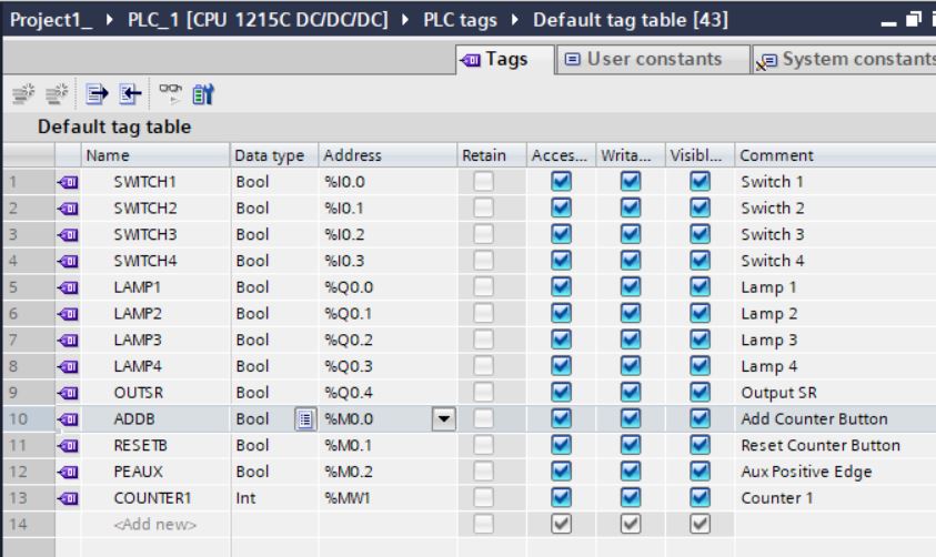
• Insert tags in Default tag table:
| ADDB | BOOL | %M0.0 | Add Counter Button |
| RESETB | BOOL | %M0.1 | Reset Counter Button |
| PEAUX | BOOL | %M0.2 | Aux Positive Edge |
| COUNTER1 | INT | %MW1 | Counter 1 |
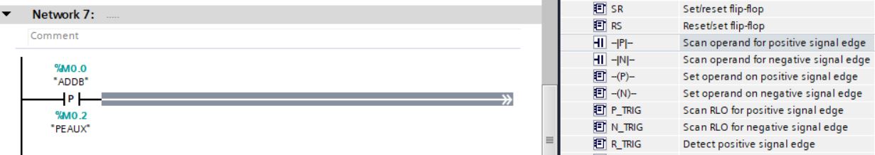
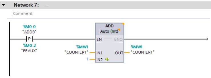
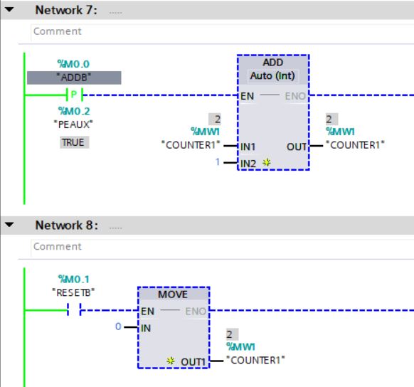
Network 7
• Insert Scan operand for positive signal edge instruction located in Basic Instructions > Bit logic operations with ADDB tag. The PEAUX tag stores the signal from the previous ADDB query.
• Insert ADD instruction located in Basic Instructions > Math functions.
When the BADD status is from logic level “0” to logic level “1”, the ADD instruction adds 1 to the COUNTER1 tag. The ADD instruction will be activated (set) for 1 scan.
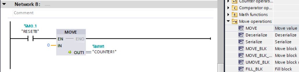
Network 8
• Insert Normally open contact instruction located at Basic Instructions > Bit logic operations with RESETB tag.
• Insert MOVE instruction Move value located in Basic Instructions > Move operations.
When the RESETB status is at logic level 1, the MOVE instruction moves 0 to the value of the COUNTER1 tag.
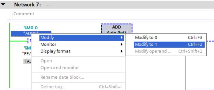
• Save project, download to simulator and test logic. Right-click the memory tag you want to change the value of and select Modify > Modify to 0 and Modify > Modify to 1.
• Click on the Stop forcing button (seventh button of the Force table). Click on the Yes button.
• Right-click on PLC_1 and select menu item Go offline.
S7-1200
CPU operating modes
The CPU has three operating modes: STOP mode, STARTUP mode and RUN mode. Status LEDs on the front of the CPU indicate the current operating mode.
• In STOP mode, the CPU does not run the program. You can download a project.
• In STARTUP mode, startup OBs (if present) run once. The CPU does not process process interrupt events during startup mode.
• In RUN mode, program cycle OBs are executed repeatedly. Interrupt events can occur and the corresponding interrupt event OBs can execute at any point within the RUN mode. You can unload some parts of the project in RUN mode.
The CPU supports a warm restart when entering RUN mode. Warm restart does not include a memory reset.
The CPU initializes all non-retentive user and system data on warm restart, and retains the values of all user retentive data.
A memory reset clears all working memory (work memory), clears retentive and non-retentive memory areas, copies load memory to work memory and activates the outputs according to the "Reaction to CPU STOP" parameter. A memory reset does not clear the diagnostics buffer or permanently saved IP address values.
You can set the CPU's "startup after POWER ON" item. This configuration item appears in "Device configuration" for the CPU in "Startup".
Upon power-up, the CPU performs a sequence of power-up and system boot diagnostic checks.
During system startup, the CPU deletes all non-retentive bits (M) memory and "resets" all content of non-retentive DBs (data blocks) to the initial values of load memory. The CPU retains the memory of the retentive bit (M) and the retentive content of DBs and then enters the appropriate mode of operation.
Certain detected errors prevent the CPU from entering RUN mode. The CPU supports the following configuration options:
• No restart (stay in STOP mode)
• Warm restart - RUN
• Warm restart - mode prior to POWER OFF

The CPU may enter STOP mode due to repairable faults such as a replaceable signal module failure, or temporary faults such as a power line disturbance or erratic start-up event. Such conditions could result in property damage. If you set the CPU to "Warm restart - mode prior to POWER OFF", the CPU goes to the operating mode it was in before the power loss or failure. If the CPU was in STOP mode at the time of the power failure or failure, the CPU switches to STOP mode on power-up and remains in STOP mode until it receives a command to go into RUN mode. If the CPU was in RUN mode at the time of the power failure or failure, the CPU will go into RUN mode on the next power up, provided it does not detect errors that inhibit a transition to RUN mode. Set the CPUs that should operate independently of a STEP 7 connection to "Warm restart - RUN" so that the CPU can return to RUN mode on the next power cycle.
In STOP mode, the CPU handles any communication requests (as appropriate) and performs self-diagnosis. The CPU does not run the user program and automatic process image updates do not occur.
In STARTUP and RUN modes, the CPU performs the tasks shown in the following image:|

A - Clears I memory area (image).
B - Initializes the memory area of the Q output (picture) with zero, the last value or the substitute value, as configured, and resets the PB, PN and AS-i outputs.
C - Initializes non-retentive M memory and data blocks to their initial value and enables configured cyclic interrupt and time of day events. Runs the startup OBs.
D - Copy the state of physical inputs to I memory.
E - Stores any interrupt events in the queue to be processed after entering RUN mode.
F - Enables the writing of Q memory to the physical outputs.
1 - Writes Q memory to physical outputs.
2 - Copy the state of physical inputs to I memory.
3 - Executes the program cycle OBs.
4 - Performs self-test diagnostics.
5 - Process interrupts and communications during any part of the scan cycle.
Download in RUN mode
The "Download in RUN mode" feature allows you to make changes to a program and download them to your CPU without switching to STOP mode:
• You can make small changes to your current process without having to stop (shut down) (for example, changing a parameter value).
• You can debug a program faster with this feature (for example, inverting the logic of a normally open or normally closed switch).
You can make the following program block and tag changes and download them in RUN mode:
• Create, replace and delete Functions (FC), Function Blocks (FB) and Tag Tables.
• Create, delete and replace Data Blocks (DB) and instance data blocks for Function Blocks (FB). You can add to DB (data block) structures and download them in RUN mode. The CPU can keep the values of existing block tags and initialize new data block tags to their initial values, or the CPU can set all tags in the data block to initial values, depending on your settings. You cannot download a DB web server (control or fragment) in RUN mode.
• Overwrite Organization Blocks (OB); however, you cannot create or delete OBs.
You can download a maximum number of twenty blocks in RUN mode at one time. If you need to download more than twenty blocks, you should put the CPU in STOP mode.
If you download changes to a real process (as opposed to a simulated process, which can be done while debugging a program), it is vital to think about the possible safety consequences for machines and machine operators before downloading.
Cycle
You can enter a maximum scan cycle monitoring time. You can also enable and enter a minimum scan cycle time.

Cycle time monitoring and configuration
Cycle time is the time the CPU operating system needs to execute the cyclic phase of the RUN mode. The CPU provides two methods of monitoring cycle time:
• Maximum scan cycle time
• Minimum scan cycle time
Scan cycle monitoring starts after the startup event is completed. The configuration for this feature appears in "Device Configuration" for the CPU in "Cycle Time".
The CPU always monitors the scan cycle and reacts if the maximum scan cycle time is exceeded. If the configured maximum scan cycle time is exceeded, an error will be generated and handled in two ways:
• If the user program does not include a time error interrupt OB, then the timer error event generates a diagnostic buffer entry, but the CPU remains in RUN mode. You can change the CPU setting to go to STOP mode when it detects a timing error, but the default setting is to stay in RUN mode.
• If the user program includes a time error interrupt OB, the CPU executes it.
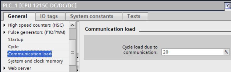
Communication load
You can configure a percentage of time to be devoted to communication tasks.
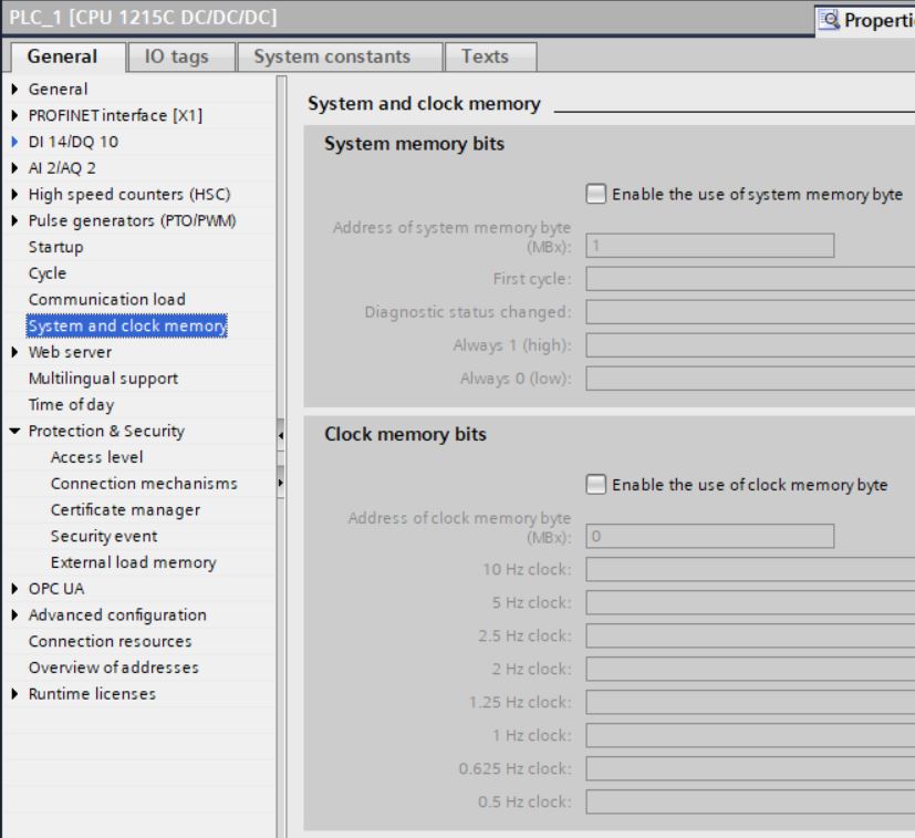
System and clock memory
You use CPU properties to enable bytes for "system memory" and "clock memory". Your program logic can reference the individual bits of these functions by their tags. You can assign a byte in M memory to system memory.
The system memory byte provides the following four bits that can be referenced by the user program by the following tags:
• First cycle: The bit (tag name "FirstScan") is set to 1 for the duration of the first scan after the initialization OB completes. After the first scan is performed, the "first scan" bit is set to 0.
• Diagnostic Status Changed (Tag Name: "DiagStatusUpdate") is set to 1 for a scan after the CPU logs a diagnostic event. Since the CPU does not set the "diagnostic graph changed" bit to "1" until the end of the first execution of the program cycle OBs, your user program cannot detect whether there has been a diagnostic change during the execution of the initialization OBs or the first execution of the program cycle OBs.
• Always 1 (high): The bit ("AlwaysTRUE" tag name) is always set to 1.
• Always 0 (Low): The bit ("AlwaysFALSE" tag name) is always set to 0.
You can assign a byte in M memory to clock memory.
Each bit of the byte configured as clock memory generates a square wave pulse. The clock memory byte provides 8 different frequencies from 0.5 Hz (slow) to 10 Hz (fast).
You can use these bits as control bits, especially when combined with edge instructions, to trigger actions in the user program in a cyclic fashion.
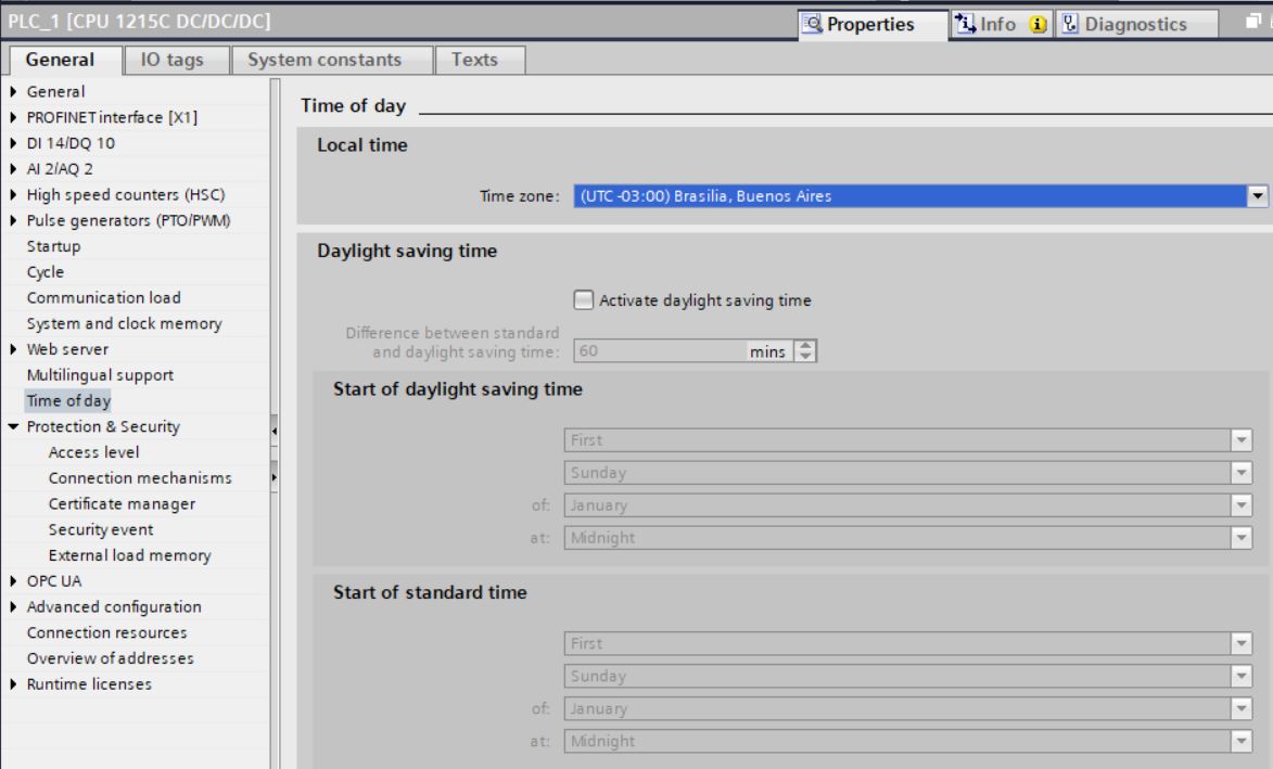
Time of Day
The CPU supports a time of day clock. A supercapacitor provides the power needed to keep the clock running during times when the CPU is turned off. The supercapacitor charges while the CPU has power. After the CPU has been powered on for at least 24 hours, the supercapacitor will have enough charge to keep the clock running normally for 20 days. STEP 7 adjusts the time of day clock to system time.
To use the time of day clock, you must set it. Date/time timestamps, such as those for diagnostic buffer entries, data log files, and data log entries, are based on system time. You set the time of day in the "Set time of day" function in the "Online & diagnostics" view of the CPU online.
STEP 7 calculates the system time from the time you set plus or minus the Windows operating system offset from UTC (Coordinated Universal Time). Setting the time of day to current local time produces a UTC system time if the Windows operating system settings for time zone and daylight saving time match your locale.
Diagnostics Buffer
The CPU supports a diagnostic buffer that contains an entry for each diagnostic event. Each entry includes a date and time the event occurred, an event category, and a description of the event. Entries are displayed in chronological order with the most recent event at the top. Up to 50 most recent events are available in this log. When the log is full, a new event replaces the oldest event in the log. When power is lost, events are saved.
The following types of events are logged in the diagnostic buffer:
• Each system diagnostic event; for example CPU errors and module errors.
• Every CPU state change (every power-up, every transition to STOP, every transition to RUN).
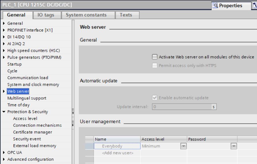
Web Server
The Web Server for the S7-1200 provides web page access to data about your CPU and process data.
You can access the S7-1200 web pages from a PC or mobile device. The web server displays pages in a format and size compatible with the device you use to access the web pages. The web server supports a minimum resolution of 240 x 240 pixels.
Project 1
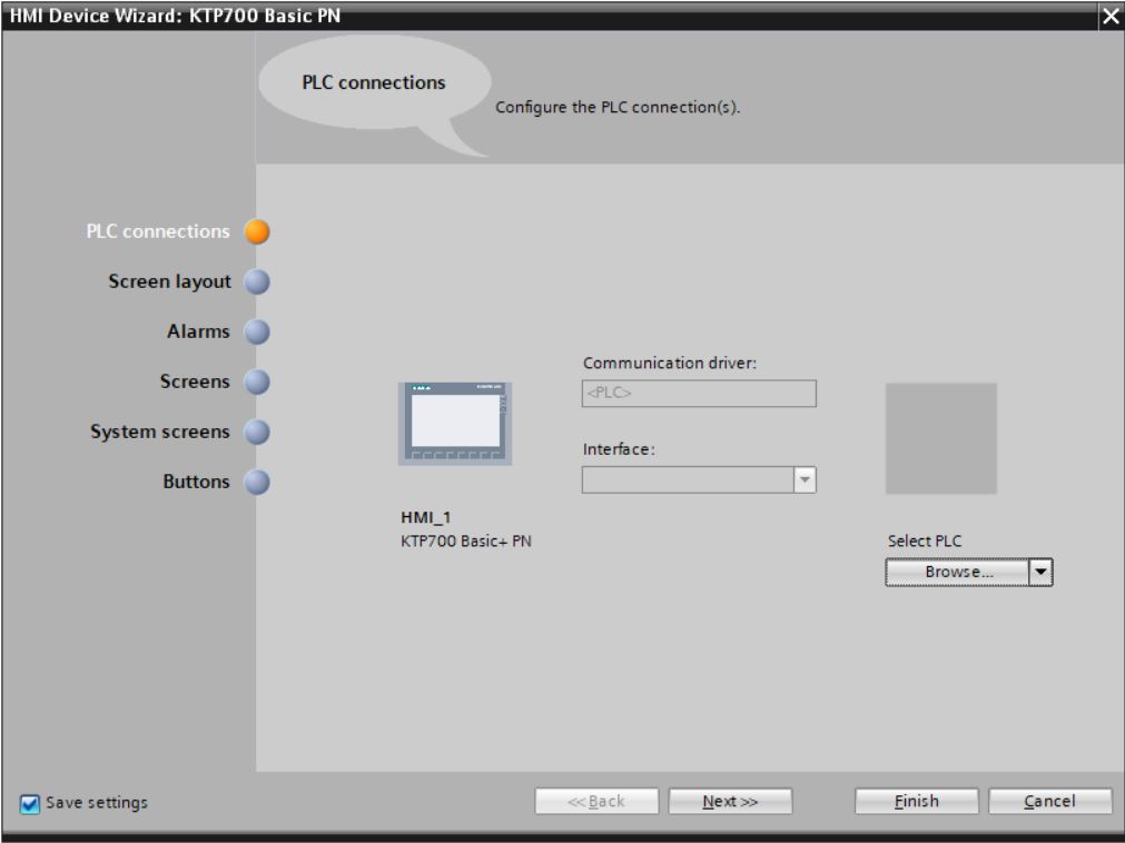
• Insert 7” KTP700 HMI device.
• Click on Add new device in Project tree > Devices > Project1.
• Enter device name (HMI_1). Select HMI > SIMATIC Basic Panel > 7” Display > KTP700 Basic PN (6AV2 123-2GB03-3AX0) version 16.0. Click on OK button.
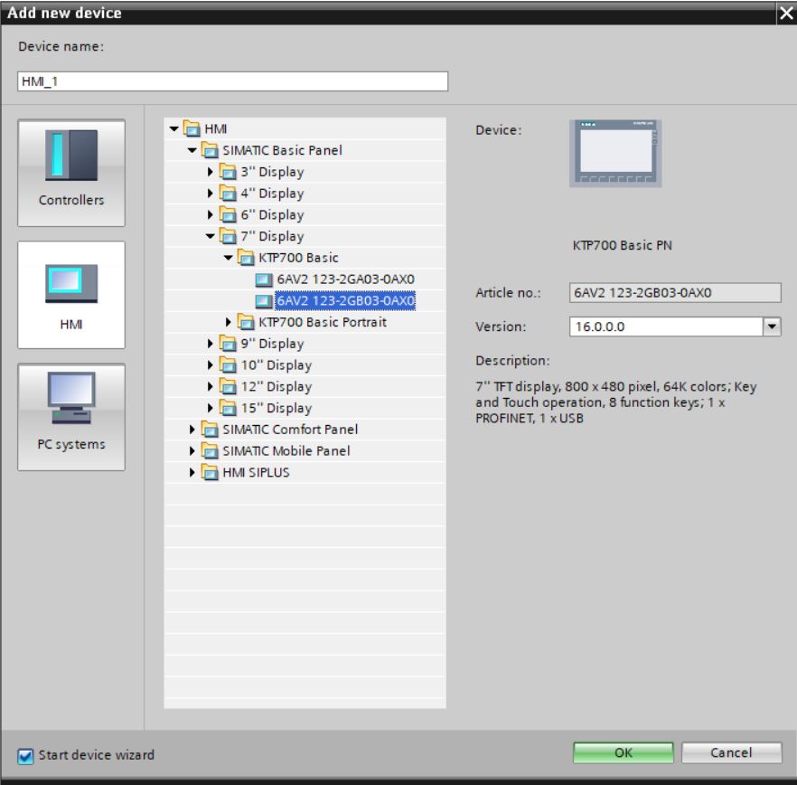
• Click on Finish button.
Comunicação entre devices
A base de todo tipo de comunicação é sempre uma rede previamente configurada. A configuração da rede necessita dos seguintes requisitos para a comunicação:
• Todos os devices em uma rede recebem um endereço exclusivo
• Comunicação dos devices com consistentes propriedades de transmissão
Os seguintes passos são necessários ao configurar redes:
• Conectar devices à subnet
• Especificar as propriedades/parâmetros de cada subnet
• Especificar as propriedades de device para cada módulo interligado
• Descarregar dados configurados para os devices
• Documentar a configuração de rede
Os devices interligados devem estar em um mesmo projeto.
Interligar devices na network view
Há diversas maneiras de configurar a rede para um componente capaz de comunicação. Os procedimentos são:
• Criar uma subnet individual
• Criar várias subnets de uma vez
• Conectar dois devices através de uma nova subnet
• Conectar devices a uma subnet existente
• Selecionar um subnet existente de uma lista
Interface
Project 1
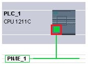
• Em Network View, clicar com o botão direito do mouse sobre a interface ETHERNET de PLC_1 e selecionar item de menu Add subnet.
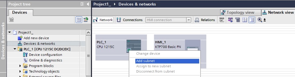
• Criada subnet PN/IE_1. Selecionar porta ETHERNET da HMI_1 e arrastar até a subnet para fazer a interconexão.
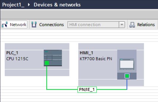
• Definir endereço IP de HMI_1 como 192.168.0.3.

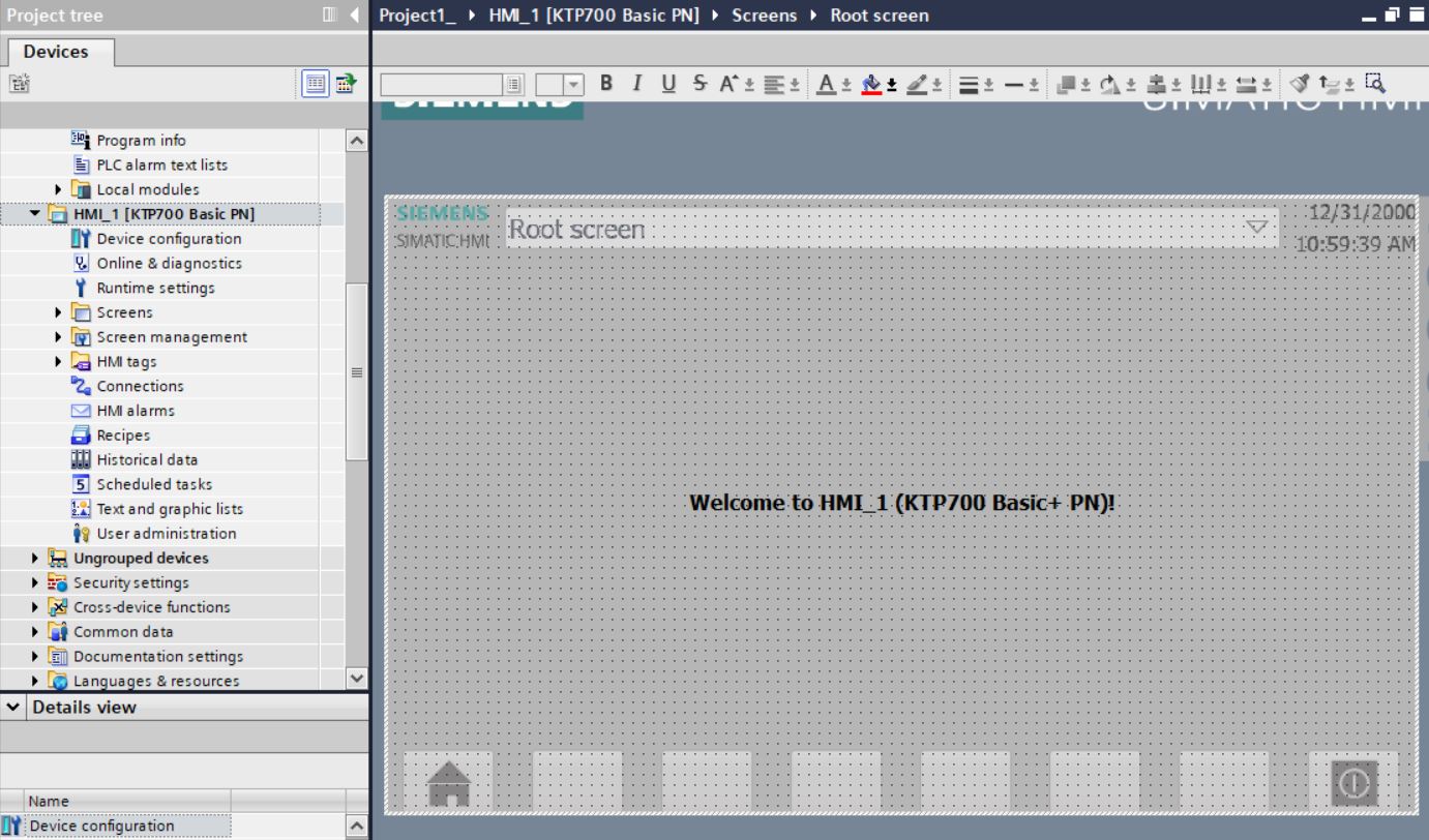
Screen
No WinCC são criadas screens (telas) que o operador usa para controlar e monitorar máquinas e plantas. Nas screens, os objetos incluídos permitem a visualização do processo, criam imagens da planta e definem valores de processo.
Uma screen consiste de elementos estáticos e dinâmicos.
Elementos estáticos como textos e objetos gráficos não mudam seus status em runtime.
Elementos dinâmicos mudam seus status baseados no processo. Os process values (valores de processo) vêm mostrados nas screens vêm da memória do PLC ou da memória do HMI device. Input fields (objeto para entrada de dados pelo operador) no HMI device é considerado um objeto dinâmico.
Process values e operator inputs são usados para transferir dados entre o controlador e o HMI device via tags.
O screen layout é determinado pelas características do HMI device que está sendo configurado. As propriedades da screen, como resolução de tela, fontes e cores, são também determinadas pelas características do HMI device selecionado. Se o HMI device tem function keys, a screen mostra estas function keys. Uma function key é uma tecla no HMI device. É possível atribuir uma ou mais functions no WinCC. Estas functions são ativadas quando o operador pressiona a tecla correspondente no HMI device.
Objetos da Screen
Objetos são elementos gráficos que são usados para desenha as screens do projeto.
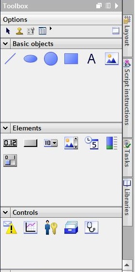
O “Toolbox” Task Card contém todos os objetos que podem ser usados no HMI device. Task Card é mostrado ativando o item de menu View > Task Card. A toolbox contém várias palhetas, dependendo do editor que está ativo. Se o “Screens” editor está aberto, a toolbox contém as seguintes palhetas:
• “Basic objects”
Os basic objects incluem objetos gráficos básicos, como “Line”, “Circle”, “Text field” e “Graphic view”.
• “Elements”
Elements incluem elementos básicos de controle, como “I/O field”, “Button” e “Gauge”.
• “Controls”
Controls apresentam funções avançadas, tais como Trend view e Recipe view.
• “Graphics”
Graphics são divididos em pastas contendo ilustrações gráficas. As pastas são Machine and plant areas, Measuring equipment, Control elements, Flags e Buildings.
• “Libraries” task card
Uma library contém objetos pré-configurados, tais como gráficos de tubulação, bombas ou botões pré-configurados. Várias instâncias do objeto podem ser integradas ao projeto sem a necessidade de reconfigurá-los.
Projeto 1
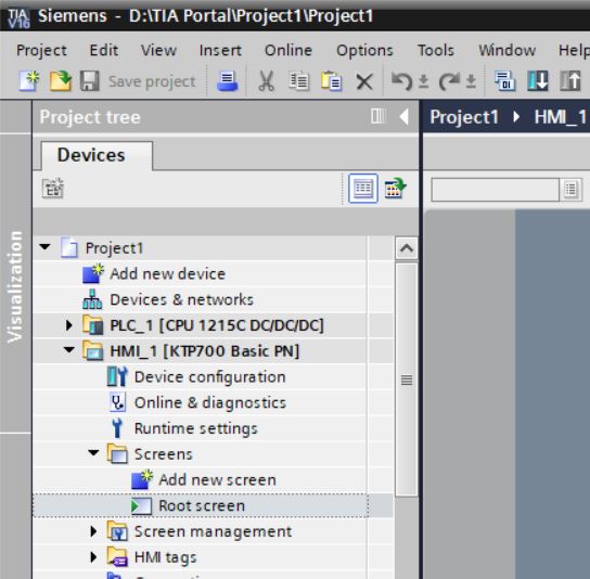
• Abrir Root screen para edição. Project tree > Devices > HMI_1 > Screens > Root screen (duplo clique).
Toolbox para edição de screen:
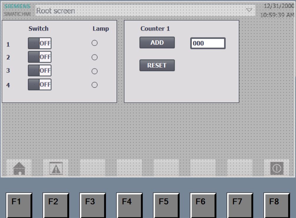
• Editar Root screen:
Next Unregistered user. Buy the training at jats.com.br.