Reactor Project
The Reactor project contains two reactors (R310 and R320). These Reactors are fed with three different types of products stored in M110, M120 and M130 tanks (Material Tanks). The product of the reactors is discharged into a B410 tank (Buffer Tank).
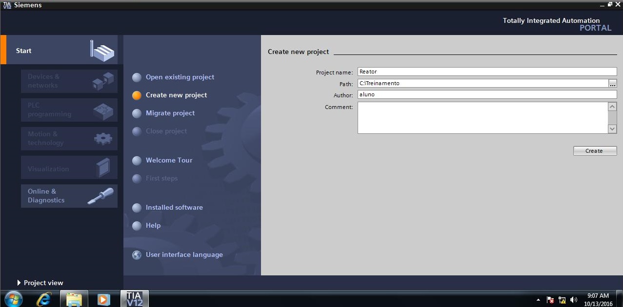
• Open Siemens TIA Portal.
• In the Start window, select Create new project element. Inform name of the project (Reactor), Path (storage location) and Author. Click on the Create button.
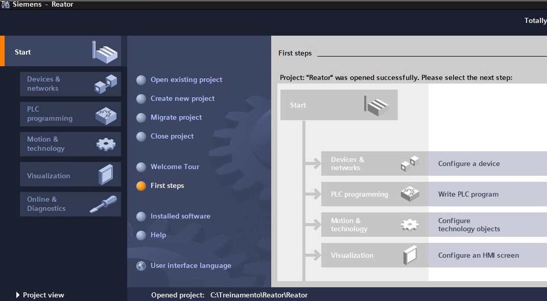
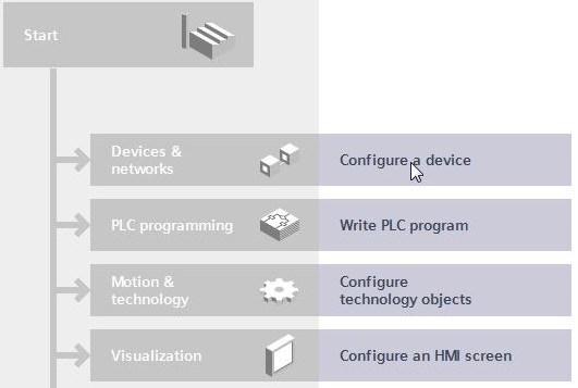
• The project is created and the first steps are shown: Devices & networks, PLC programming, Motion & technology and Visualization.
• Click on Configure a device.
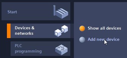
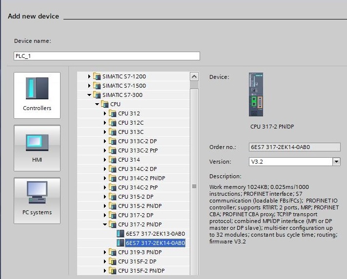
• The devices will be presented (none at the time). Click on Add new device.
• Inform the Device name (PLC_1). Select the controller in Controllers > SIMATIC S7-300 > CPU & gt; CPU 317-2 PN/DP > 6ES7 317-2EK14-0AB0. Click on the Add button.
• Project created.
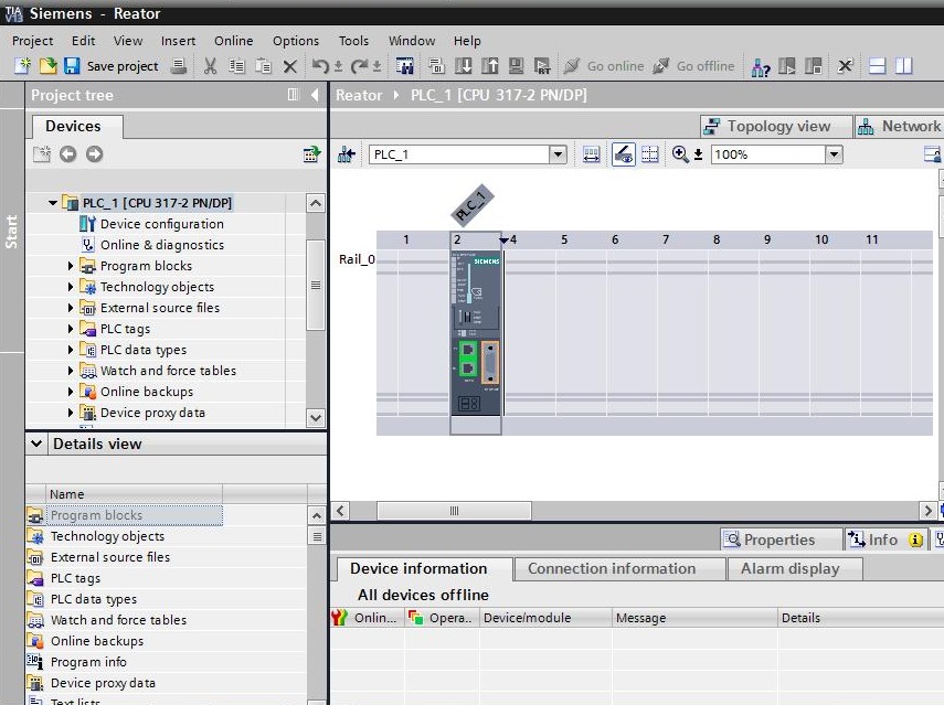
• Save the project by clicking on the Save project button or through the Project > Save menu.
• Close the project (Project > Close menu) or close the application (Project > Exit menu).
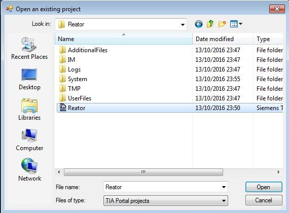
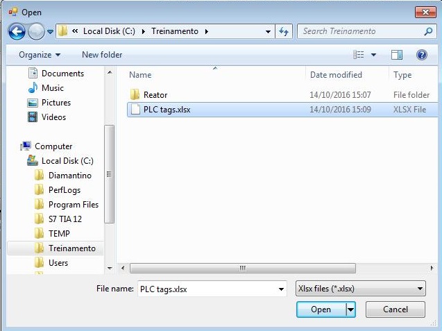
• Reopen the project. Select Project > Open menu ... or, if the project has been recently opened, a shortcut will appear at the end of the menu (highlighted in red).

• By selecting the Open... menu item, a dialog box will appear and the storage location and the project to be opened should be selected.
Hardware Configuration
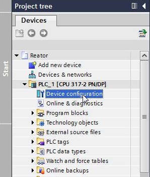
• Open Device Configuration (double click on Project tree > Devices > Reactor > PLC_1 > Device Configuration).
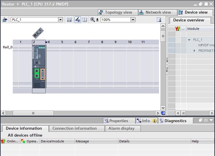
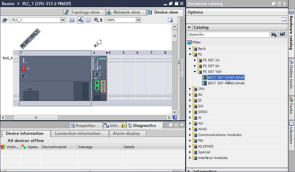
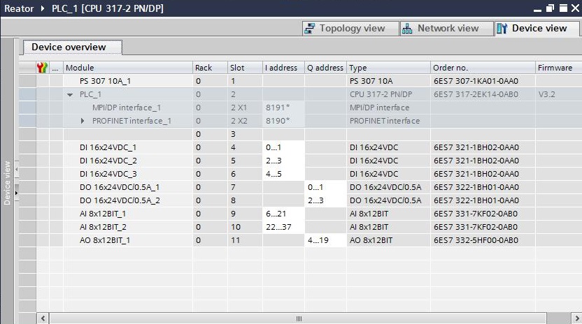
• Insert PS 307 10A 6ES7 307-1KA01-0AA0 source. Open Hardware Catalog > Catalog > PS > PS 307 10A. Select 6ES7 307-1KA01-0AA0 and drag to position 1 of the rack. Or select previously position 1 of the rack and double click on 6ES7 307-1KA01-0AA0 object.
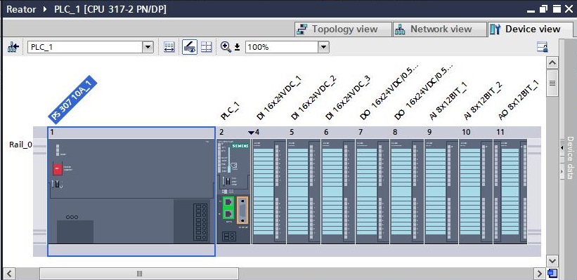
• Insert 3 modules of 16 digital inputs in slots 4 to 6. Open Hardware Catalog > Catalog > DI > DI 16x24VDC. Select 6ES7 321-1BH02-0AA0 and drag to position 4 of rack. Repeat the procedure for slots 5 and 6.
• Insert 2 modules of 16 digital outputs in slots 7 and 8. Open Hardware Catalog > Catalog > DQ > DQ 16x24VDC/0.5A. Select 6ES7 322-1BH01-0AA0 and drag to position 7 of the rack. Repeat the procedure for slot 8.
• Insert 2 modules of 8 analog inputs into slots 9 and 10. Open Hardware Catalog > Catalog > AI > AI 8x12BIT. Select 6ES7 331-7KF02-0AB0 and drag to position 9 of the rack. Repeat the procedure for slot 10.
• Insert 1 module of 4 analog outputs in slot 11. Open Hardware Catalog > Catalog > AQ > AQ 4x12BIT. Select 6ES7 332-5HF00-0AB0 and drag to position 11 of the rack.
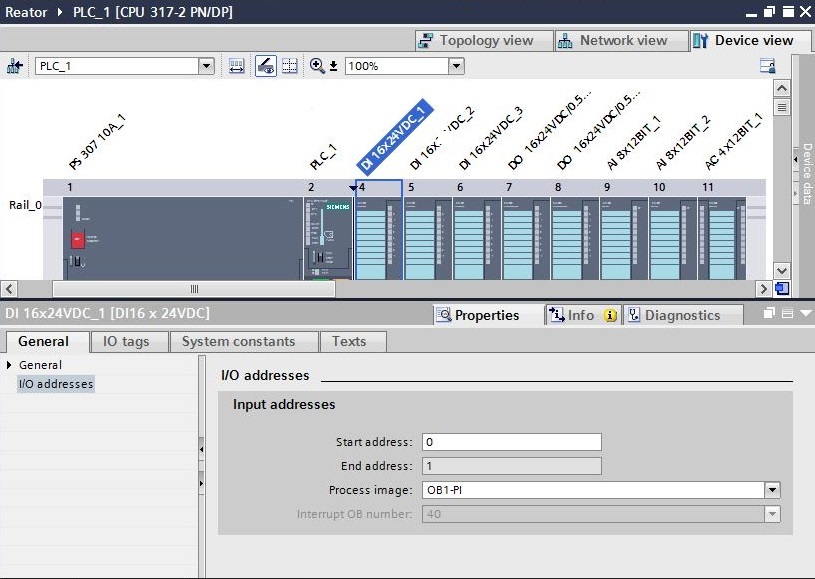
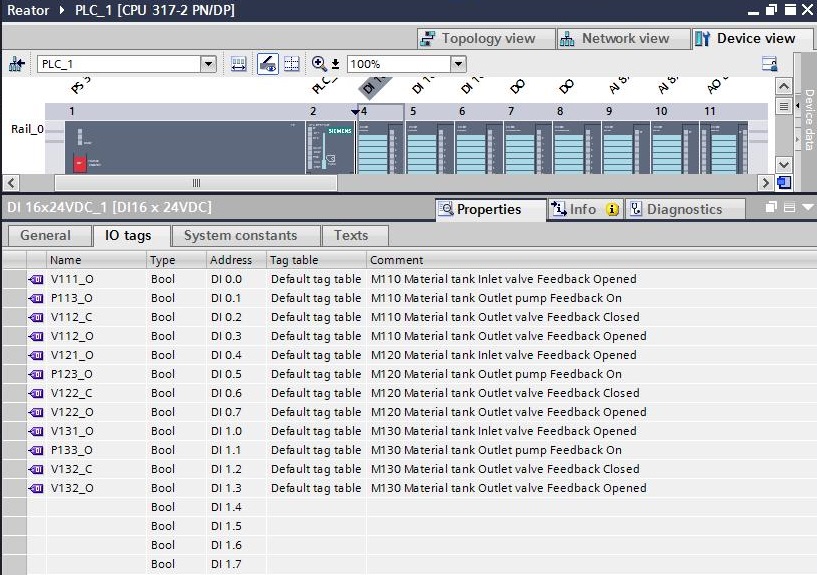
• Enter with I/O tags in the input and output modules. Open the properties of the rack digital input module PLC_1 slot 4 (click on the module with the right mouse button and select the Properties menu item).
• Open General tab - I/O address and observe the input address of the module. Start address = 0.
• Open IO tags tab and report name and comment of each module channel.
| Name | Type | Address | Comment |
|---|---|---|---|
| V111_O | Bool | DI 0.0 | M110 Material tank Inlet valve Feedback Opened |
| P113_O | Bool | DI 0.1 | M110 Material tank Outlet pump Feedback On |
| V112_C | Bool | DI 0.2 | M110 Material tank Outlet valve Feedback Closed |
| V112_O | Bool | DI 0.3 | M110 Material tank Outlet valve Feedback Opened |
| V121_O | Bool | DI 0.4 | M120 Material tank Inlet valve Feedback Opened |
| P123_O | Bool | DI 0.5 | M120 Material tank Outlet pump Feedback On |
| V122_C | Bool | DI 0.6 | M120 Material tank Outlet valve Feedback Closed |
| V122_O | Bool | DI 0.7 | M120 Material tank Outlet valve Feedback Opened |
| V131_O | Bool | DI 1.0 | M130 Material tank Inlet valve Feedback Opened |
| P133_O | Bool | DI 1.1 | M130 Material tank Outlet pump Feedback On |
| V132_C | Bool | DI 1.2 | M130 Material tank Outlet valve Feedback Closed |
| V132_O | Bool | DI 1.3 | M130 Material tank Outlet valve Feedback Opened |
• Define start addresses for all modules:
16DI PLC_1 Slot 4 – Start address = 0;
16DI PLC_1 Slot 5 – Start address = 2;
16DI PLC_1 Slot 6 – Start address = 4;
16DQ PLC_1 Slot 7 – Start address = 0;
16DQ PLC_1 Slot 8 – Start address = 2;
8AI PLC_1 Slot 9 – Start address = 6;
8AI PLC_1 Slot 10 – Start address = 22;
4AQ PLC_1 Slot 11 – Start address = 4;
• Insert inputs and outputs of the other modules. The IO tags can be inserted manually in each channel of each module or by importing an .xlsx file with the IO tags to insert.
Import of Tags
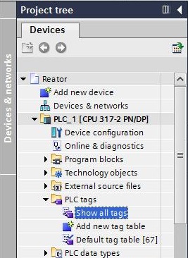
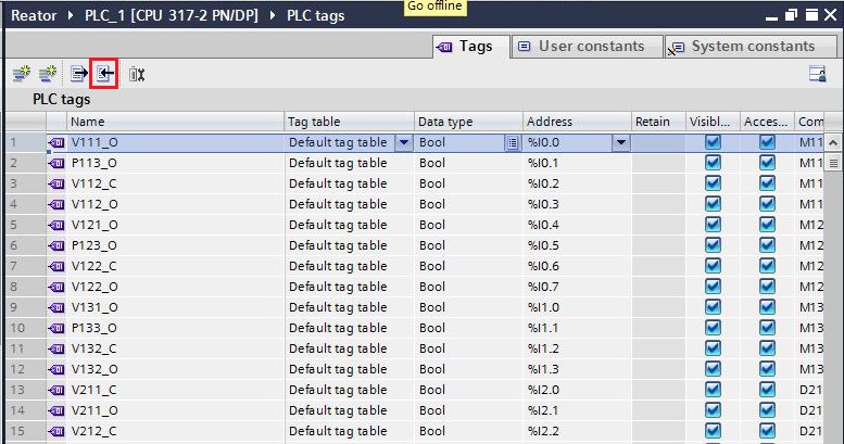
• Show all tags. Select Project tree > Devices > Reactor > PLC_1 > PLC tags > Show all tags.
• All PLC_1 tags are displayed. Select Import button of the toolbar (in red).
• Search Excel file (.xlsx format) to be imported into the computer.
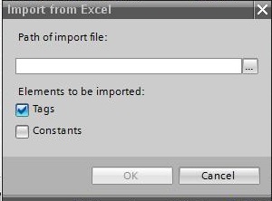
• Select PLC tags.xlsx file. Import only Tags.
• PLC file tags.xlsx. The IO tags of the first module digital files are not found in this file, since it is inserted manually.

| Name | Type | Address | Comment |
|---|---|---|---|
| V211_C | Bool | DI 2.0 | D210 Dose tank Inlet valve 1 Feedback Closed |
| V211_O | Bool | DI 2.1 | D210 Dose tank Inlet valve 1 Feedback Opened |
| V212_C | Bool | DI 2.2 | D210 Dose tank Inlet valve 2 Feedback Closed |
| V212_O | Bool | DI 2.3 | D210 Dose tank Inlet valve 2 Feedback Opened |
| V213_C | Bool | DI 2.4 | D210 Dose tank Inlet valve 3 Feedback Closed |
| V213_O | Bool | DI 2.5 | D210 Dose tank Inlet valve 3 Feedback Opened |
| Name | Type | Address | Comment |
|---|---|---|---|
| V311_C | Bool | DI 4.0 | R310 Reactor Inlet valve Feedback Closed |
| V311_O | Bool | DI 4.1 | R310 Reactor Inlet valve Feedback Opened |
| P313_O | Bool | DI 4.2 | R310 Reactor Outlet pumb Feedback On |
| V312_C | Bool | DI 4.3 | R310 Reactor Outlet valve Feedback Closed |
| V312_O | Bool | DI 4.4 | R310 Reactor Outlet valve Feedback Opened |
| M316_O | Bool | DI 4.5 | R310 Reactor Stirring motor Feedback On |
| Name | Type | Address | Comment |
|---|---|---|---|
| P113_Q | Bool | DQ 0.0 | M110 Material tank Outlet pump |
| V112_Q | Bool | DQ 0.1 | M110 Material tank Outlet valve |
| P123_Q | Bool | DQ 0.2 | M120 Material tank Outlet pump |
| V122_Q | Bool | DQ 0.3 | M120 Material tank Outlet valve |
| P133_Q | Bool | DQ 0.4 | M130 Material tank Outlet pump |
| V132_Q | Bool | DQ 0.5 | M130 Material tank Outlet valve |
| V211_Q | Bool | DQ 0.6 | D210 Dose tank Inlet valve 1 |
| V212_Q | Bool | DQ 0.7 | D210 Dose tank Inlet valve 2 |
| V213_Q | Bool | DQ 1.0 | D210 Dose tank Inlet valve 3 |
| Name | Type | Address | Comment |
|---|---|---|---|
| V311_Q | Bool | DQ 2.0 | R310 Reactor Inlet valve |
| P313_Q | Bool | DQ 2.1 | R310 Reactor Outlet pump |
| V312_Q | Bool | DQ 2.2 | R310 Reactor Outlet valve |
| M316_Q | Bool | DQ 2.3 | R310 Reactor Stirring motor |
| Name | Type | Address | Comment |
|---|---|---|---|
| LT114_AI | Word | IW 6 | M110 Material tank Level |
| LT124_AI | Word | IW 8 | M120 Material tank Level |
| LT134_AI | Word | IW 10 | M130 Material tank Level |
| LT214_AI | Word | IW 12 | D210 Dose tank Level |
| Name | Type | Address | Comment |
|---|---|---|---|
| LT314_AI | Word | IW 22 | R310 Reactor Level |
| TT315_AI | Word | IW 24 | R310 Reactor Temperature |
| Name | Type | Address | Comment |
|---|---|---|---|
| CV315_AQ | Word | QW 4 | R310 Reactor temperature control valve |
Remote 1
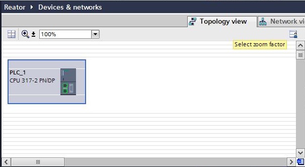
• Insert Remote 1. In Device Configuration, click on the Topology view tab.
• Insert ET 200SP. Open Hardware Catalog > Catalog > Distributed I/O > ET 200SP > Interface modules > PROFINET > IM 155-6 PN ST. Select 6ES7 155-6AU00-0BN0 and drag to Topology view area.
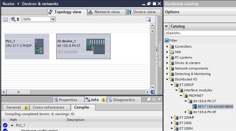
• Rename IO device ET 200SP to Remote_1. Open Project tree > Devices > Reactor > Unassigned devices. Right-click on IO device_1 and select Rename menu item. Change name to Remote_1.

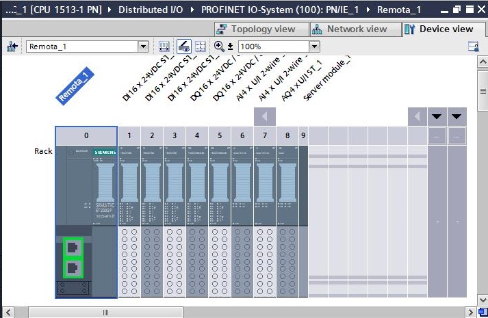
• Insert IO modules in Remote_1. Select Remote_1 in the Topology view and then click on the Device view tab.
• Insert 3 modules of 16 digital inputs in slots 1 to 3. Open Hardware Catalog > Catalog > DI > DI 16 x 24VDC ST. Select 6ES7 131-6BH00-0AB0 and drag to slot 1 of the remote. Repeat procedure for slots 2 and 3. Open properties of the module in slot 3 (Properties > General tab > Potential Group and select the option Enable new potential group. For every two I/O modules in the ET 200SP, a potential group is created (slots groups 1-2, 3-4, 5-6, 7-8). The option Enable new potential group opens a new group (the terminal of the module appears in light color). The Use potential group of the left module option includes the module in the same module group to the left of it (the module's terminal appears in dark color).
A potential group consists of a group of directly adjacent I/O modules within an ET200SP station, which are fed through a common voltage. A potential group starts with a light-colored BaseUnit, through which the required voltage is provided for all modules in the group. A potential group ends with the dark-colored baseUnit, which is followed by a light BaseUnit color or server module in the station's configuration.

• Insert 2 modules of 16 digital outputs in slots 4 and 5. Open Hardware Catalog > Catalog > DO > DO 16 x 24VDC / 0.5A ST. Select 6ES7 132-6BH00-0AB0 and drag to remote slot 4. Repeat procedure for slot 5. Open module properties to slot 5 (Properties > General tab > Potential Group and select Enable new potential group option.
• Insert 2 modules of 4 analog inputs in slots 6 and 7. Open Hardware Catalog > Catalog > AI > AI4 x U/I 2-wire ST. Select 6ES7 134-6HD00-0AB1 and drag to remote slot 6. Repeat procedure for slot 7. Open module properties to slot 7 (Properties > General tab > Potential Group and select Enable new potential group option.
• Insert 1 module of 4 analog outputs in slot 8. Open Hardware Catalog > Catalog > AO > AO 4xU/I ST. Select 6ES7 135-6HD00-0AB1 and drag to remote slot 8.
• Insert Server module to finish the remote. Open Hardware Catalog > Catalog > Server modules. Select 6ES7 193-6PA00-0AA0 and drag to remote slot 9.
• PLC_1 Device overview.

Next Unregistered user. Buy the training at jats.com.br.