Ladder Diagram Language
The operation of the CLP is based on a set of instructions known as a program, developed to address user routines. The signals from the sensors or transducers coupled to the machine or equipment are applied to the controller inputs. In each cycle, called scanning or scanning, there are three stages:
• Input stage – All signals coming from external media and applied to the inputs are read and transferred to a CLP internal memory unit zone, called an input image table.
• Program stage - The program is executed using the signals acquired during the input stage and deciding what the values of the digital and analog output signals will be. These values are stored in a memory region called the output image. During program execution, the output signals are not modified unless high priority inputs are activated. These entries are used for emergencies, which are not They can wait for the end of scanning. In that case, we interrupt the work of the CLP, executing a program that addresses interruption. After the interruption service, we return to the main program.
• Output stage – All output values set by the program and stored in the output image are applied to the output modules.
At the end of the three steps, the scan cycle is restarted, with the input step (cyclic operation). In some situations, for example, when using PID controllers, it becomes necessary to make the signal acquisitions (input step) at fixed intervals. In this case, at the end of the exit stage, the PLC waits for the predetermined instant to restart the scan (periodic operation).
There are several programming languages for PLC, which, using a set of symbols, blocks, figures, commands, etc., allow the programmer to manifest the relationships between the inputs and outputs of the PLC.
In the current generation of PLC, high-level languages are used, which have a series of predefined programming instructions. This approximates the high-level languages of human language, thus facilitating the work of the programmer. The so-called low-level programming languages, or in machine language, require greater skill of the programmer, which will need a good understanding of the hardware of the equipment, programming bit by bit, as is the case of assembly language.
The Ladder language reproduces the structure of an electrical diagram, in which the combination of open contacts, corresponding to the inputs, will allow to energize a certain load, which corresponds to the output.
Depending on the proximity of the Ladder language with the logic of Relays, widely used before the emergence of PLCs, this has become one of the most used languages by PLC manufacturers.
Basic instructions in Ladder
The basic or fundamental instructions in the Ladder language are:
NO Contact: normally open; The following image shows the NA contact instruction on stairs, as well as the electrical circuit and the correspondent digital logic.

Note that in the NO Contact instruction, the status of the digital output is identical to that of the digital input. So, when I1 is high level, output Q1 will be activated; and when I1 is at the low level, output Q1 is disabled. The following image shows the PLC installation circuit.

NC Contact: normally closed; The following image shows the NA contact instruction on stairs, as well as the electrical circuit and the correspondent digital logic.

Note that, in the NF Contact instruction, the state of the digital output is inverse to that of the digital input. therefore, when I1 is at a high level, output Q1 is disabled; and when I1 is at a low level, output Q1 is activated.
AND: The image shows the AND function in Ladder, as well as the electrical circuit and the corresponding digital logic.

Note that, in function E, the status of the digital output depends on the combination of the digital inputs. therefore, when I1 and I2 are simultaneously at a high level, output Q1 will be activated; and, when either of the inputs, or both, are down level, the Q1 output will be deactivated. The following image shows the CLP installation circuit for the program.

OR: The image shows the staircase OU function, as well as the electrical circuit and the corresponding digital logic.

Note that, in the OU function, the status of the digital output depends on the combination of the digital inputs. therefore, when I1 or I2, or both, are at a high level, output Q1 will be activated; and, only when I1 and I2 are simultaneously at a low level, will we have output Q1 disabled.
Project1
• Insert S2 tag of type BOOL and description Switch 2 and L2 tag of type BOOL and description Lamp 2. The switch S2 is a normal closed contact. When it is not activated, its contacts are closed allowing the passage of current. When activated, its contacts open preventing the passage of current.

• Insert line into MainRoutine with S2 normal closed contact by activating the L2 lamp at the output. To create a new line, click on the end line End and press the Insert key.

• Save the project and download it to the emulator. Test the changes by opening and closing the switch S2 and observing the status of the L2 lamp.
• S2 switch disabled (logic level "0") and lamp on (logic level "1").

• Observe in Controller Tags > Monitor Tags S2 with logic level "0" and L2 lamp with logic level "1".

• Change the logic level from S2 to "1" (Toggle).
• S2 switch activated (logic level "1") and lamp off (logic level "0").

• Observe in Controller Tags > Monitor Tags S2 with logic level “1” and L2 lamp with logic level “0”.

Ladder
NO-NC Serial Instructions
The following image shows the NO-NC series stair function, as well as the electrical circuit and the corresponding digital logic.

Note that, in the serial NO-NC function, the status of the digital output depends on the combination of the digital inputs. Thus, only when I1 is high and I2 low level, will we have output Q1 activated. For any other situation, we will have the Q1 output disabled.
NO-NC Parallel Intructions
The following image shows the parallel ladder NO-NC function, as well as the electrical contact and the corresponding digital logic.

Note that, in the parallel NO-NC function, the status of the digital output depends on the combination of digital inputs. Therefore, only when I1 is low and I2 is high, will we have output Q1 disabled. For any other situation, we will have the output Q1 activated.
• Insert L3 tag of type BOOL and description Lamp 3 and L4 tag of type BOOL and description Lamp 4. Insert line into MainRoutine with S1 normal open contact in series with S2 normal open contact and by operating L3 lamp.

• Save the project and download it to the emulator. Test the changes by opening and closing keys S1 and S2 and observing the status of the L3 lamp. Since S1 and S2 are connected in series, the L3 lamp only comes on when the two contact are closed (logic level "1").

• Insert line in MainRoutine with S1 normal open contact in parallel with S2 normal open contact and by operating L4 lamp.

• Save the project and download it to the emulator. Test the changes by opening and closing the S1 and S2 switches and observing the status of the L4 lamp. Since S1 and S2 are connected in parallel, lamp L3 comes on when one of the switches is closed (logic level "1") or when both switches are closed at the same time.

• Given the following circuit, obtain the corresponding circuit in Ladder language.
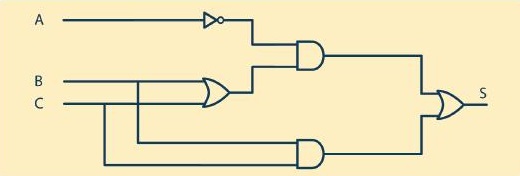
NOT logic symbol (output receives the inverted signal from the input):

AND logic symbol:

OR logic symbol:

• Insert the tags in Controller Tags:
| InA | BOOL | A Input |
| InB | BOOL | B Input |
| InC | BOOL | C Input |
| OutS | BOOL | S Output |
• Insert line in Main Routine with normal closed contact for InA - Input A and normal open contact for InB - Input B in series forming an AND logic.

• Insert normal open contact InC - Input C in parallel with InB, forming an OR logic (use Branch instruction).

• Insert all contacts and the OutS output coil - S Output.

• Insert a comment for Rung (line). Right click on rung 4 and select Edit Rung Comment menu item.

•Insert comment with the Boolean formula S = (NOT A AND (B OR C)) OR (B AND C).

• Simulate the logic by alternating the values of the digital inputs and observing the result in the digital output.
Special instructions
Depending on the characteristics of the PLCs, manufacturers may offer several special functions. This item will address the most commonly used special functions, once the PLC programming manual instructs the use of its programming functions.
SET Instruction
This function forces the status of a memory or a PLC output to be activated. The following image shows the SET function in Ladder.

Note that, in the SET function, the status of the digital output depends on information from the digital input. When input I1 is high, output Q1 is high. Note that, even when I1 input returns to a low level, output Q1 will remain at a high level, necessarily using another function to deactivate the output.
RESET Instruction
This function forces the status of a memory or a PLC output to be deactivated. The following image shows the RESET function in Ladder.

Note that, in the RESET function, the status of the digital output depends on information from the digital input. When I2 input is high, Q1 output will be low.
Note that when input I2 returns to a low level, output Q1 will remain at a low level.
Project1
• Insert the tags in Controller Tags:
| OutSR | BOOL | Output Set Reset |
• In MainRoutine, insert new rung with normal open contact for InA - A Input. Insert coil Set (Output Latch - L) for OutSR - Output Set Reset.

• Insert a new rung with normal contact open for InB - B Input. Insert Coil Reset (Unlatch-U Output) for OutSR - Set Reset Output.

• Simulate the Set and Reset logic by alternating the values of the digital inputs and observing the result in the digital output.
Positive Edge Contact Instruction
This instruction generates a pulse in the output associated with it. The pulse has the period of 1 scan (controller cycle) and starts when the input passes the logic level "0" to "1".

A program that uses this type of instruction can be seen in the following image.

The state diagram of the positive edge input (I0.0) and the simple output (Q0.0) demonstrates the application of this instruction. Observe, when the input (I0.0) and activated, or in the step of the logic level "0" to "1", a pulse with a duration of 1 scan appears in the output associated with that input. In the descent, in the passage of the logical level "1" to "0", nothing happens at the exit.

Negative Edge Contact Instruction
The negative edge contact instruction generates a pulse in the output associated with it. This pulse has the period of 1 scan and starts when the input goes from the logical level "1" to "0".

A program that uses this type of instruction can be seen in the following image.

The state diagram of the negative edge input (I0.0) and the simple output (Q0.0) demonstrates the application of this instruction. Note that, when the input (I0.0) and activated, nothing happens; however, when disconnected, in the step of the logical level "1" to "0", a pulse with a duration of 1 scan appears on the output associated with that input.

ONS – On Shot
The ONS instruction activates or deactivates the rest of the rung, depending on the state of the storage bit. Bit storage saves the value of the rung-condition-in input the last time the instruction was executed.
Project1
• Insert the tags in Controller Tags:
| BMON | BOOL | Motor On Button |
| BMOFF | BOOL | Motor Off Button |
| OutMON | BOOL | Motor On Command |
| OutMOF | BOOL | Motor Off Command |
| ONSMON | BOOL | Storage ONS Motor On |
| ONSMOF | BOOL | Storage ONS Motor Off |
| LMON | BOOL | Motor On Lamp |
| LMON | BOOL | Motor Off Lamp |
• In MainRoutine, insert new rung with normal open contact for BMON - Motor On button in series with ONS instruction to activate the OutMON output - Motor On command. When the BMON status is from logic level "0" to logic level "1", the OutMON output will be triggered by 1 scan.

• Insert a new rung with normal contact open for OutMON, which, when closing the contact, activates the LMON output - Motor On Lamp and deactivates LMOFF - Motor Off Lamp and BMOFF - Motor Off Button.

• Insert new rung with normal open contact for BMOFF - Motor Off Button in series with ONS instruction to activate the OutMOFF output - Motor Off command. When the status of BMOFF is from logic level "0" to logic level "1", the OutMOFF output will be triggered by 1 scan.

• Insert a new rung with normal contact open for OutMOFF, which, when closing the contact, activates the LMOFF output - Motor Lamp Off and deactivates LMON - Motor Lamp On and BMON - Motor On Button.

• Simulate the logic with ONS instruction by operating the ON and OFF motor buttons and observing the result at the outputs.
Programming languages
IEC 61131 Standard
In 1992, the International Electrotechnical Commission (IEC) published the first edition of the IEC 61131 standard, with the aim of establishing standards for programmable controllers. This standard has been divided into several chapters, enabling the definition of criteria for each of the topics related to PLCs.
The chapters are as follows:
• 61131-1 – General information about PLCs.
• 61131-2 – Hardware requirements
• 61131-3 – Programming languages.
• 61131-4 – User orientation guide.
• 61131-5 – Communication.
This standard defines that, for a PLC to be in accordance with the standards established by it, it must have less than graphic languages and text languages for programming. Thus, and consensus among the current manufacturers work with the following languages:
• Textuals:
IL – Instruction List.
ST – Structured Text.
• Graphics:
LD – Ladder Diagram.
FBD – Function Block Diagram.
A fifth way to program some market devices is the SFC - Sequential Function Chart is the graphical sequencing of functions, which has elements to organize programs sequentially and also allows parallel control of processes.
Between these programming languages, some parameters are defined so that there really is certain compatibility between the equipments. These parameters can be set as:
a) Data - The standard predicts the following types of data:
• Bit group: binary value group (on/off).
BOOL: 1 bit.
BYTE: 8 bits.
WORD: 16 bits.
DWORD: 32 bits.
LWORD: 64 bits.
• Integers: integer and real numbers.
SINT: short integer (1 byte).
INT: integer (2 bytes).
DINT: double integer (4 bytes).
LINT: long integer (8 bytes).
U: undefined (add a U character to the type of integer to be used).
• Real: floating point, that is to say, it considers fractional in the use of the number according to IEC 559 (1982).
REAL: 4 bytes.
LREAL: 8 bytes.
• Time: duration of timers and processes.
• Date and time of day.
DATE: calendar date.
TIME_OF_DAY: local time.
DATE_AND_TIME: local date and time.
• String: characters that can be exposed in single installments - normally for the transmission of ASCII (American Standard Code for Information Interchange) characters to other devices.
WSTRING: allow the sending of several strings.
ARRAYS: multiple values stored in the same variable.
SUB RANGES: set value limits for data entry or exit - for example, signals from 4 to 20 mA.
b) Variables - They can be of the type:
• Global: It serves the entire program and not necessarily only a part of it.
• Local: only part of the program.
• I/O mapping: allocation of all inputs and outputs in relation to the predefined memory positions.
• External: assignment defined exclusively as data entry and exit points.
• Temporary: used momentarily during the execution of part of the program.
c) Configuration - Hardware resources and specific links for data processing and programs.
• Resources: memory reserve or processing indexes for certain part of the program.
• Tasks: they can continue parallel, being executed simultaneously by the PCU.
• Programs: they can be executed cyclically, at every certain period or when a certain event occurs.
d) Organization of program units - Defined by the basic functions, basic blocks and possibility of creating functions and blocks according to the need for programming.
• Standard functions such as: ADD, SQRT, SIN, COS, GT, MIN, MAX, AND, OR, among others.
• Custom functions: field in which the programmer can create functions or use more than one pre-existing function for the creation of another function in its programming.
• Function blocks: patterns equal to those presented in the functions, only in block language.
• Custom blocks: field for the elaboration or use of more than one pre-existing function in the creation of blocks. They can also be composed of blocks sold by other manufacturers or specialized companies.
• Programs: specific programs and subroutines. They can be stored in functions or blocks created by the programmer and used more than once in the current application or later in other programs.
e) External links - Opens space for the IEC 61131-5 chapter, which deals specifically with the communication formats and facilities that the standard determines as necessary for the compatibility with the standard.
Ladder Programming Language
Ladder was one of the first languages destined to the programming of PLCs, created to allow technicians and engineers of the automation area with knowledge of relay logic and none of programming managed to program the PLC. For this reason, it became the most popular language among programmers.
Basic directives
The variables associated with the elements of input, output, memory, timers and counters are called operands. The program runs logical and arithmetic operations with these operands.
In the Ladder language, the lines of contacts (instructions) have the appearance of stair steps, which can be associated with a structure of columns and lines, as shown in the image below. In each line, the instructions correspond to the program, that is, the operands process, and the result and assigned to another operating in the "Output" block, to the right.

The number of rows and columns or elements and associations that each rung supports varies according to the PLC manufacturer and may also vary according to the CPU used. In general, these limits do not represent a concern to the user in the development of the application program, because, if the limit is exceeded, the programming software presented an error message during the compilation of the program.
The operands can be divided into three classes:
• Memory (M) – They are used for storing partial results, constant values, transmission data, reference values, recipes, etc.
These operands can be freely read and written by the program.
• Inputs (I) – They are associated to the input modules. They can be read by the program, but written only by the input modules.
• Outputs (Q) – They are associated with the output modules. They can be freely read and written by the program.
The operands, in turn, are divided, initially, into five types, according to their use and number of bits:
• Bits (X) – Used for logic implementation, occupy 1 bit of memory.
• Bytes (B) – Used for the storage of ASCII characters, they occupy 8 bits.
• Words (W) – Used for storing integer numerical values, they occupy 16 bits.
• Double word (D) – Like the W type, it occupies 32 bits.
• Word long (L) of 64 bits – Like the W type, it occupies 64 bits.
Originally, in the Ladder language each instruction corresponded to the NO or NC contacts of the relays, whose status is defined by the value of the operand (of type B) associated with it. At the same time, the outputs were the coils (operandotype B). Over time, the instruction blocks began to contemplate counters, timers, arithmetic operations, etc., which demanded that the types of operands mentioned above be created.
Counters
A counter aims to activate a memory or an output memory after a certain event count. The following image shows the instruction and symbology of the meter, according to IEC 1131-3.

Note that, in the counter instruction, input I1 receives pulses from external keys or sensors, sending to counter C1. In the program, C1 was parameterized for 4 accounts. After C1 receiving 4 pulses (four energies / de-energizations), the NO contact of the C1 counter closes, activating the output Q1.
The counter can be increasing, decreasing or even ascending descending (up/down). For the last purpose, the counter block is composed too much of an entry that will count down, according to the following image.

It is observed that I1 makes the account growing, I2 the account and I3 triggers the reset. The following image shows the diagram of counter times up/down.

After completing the counting cycle (4 counts), Q1 is activated, regardless of the state of I1. The output Q1 can be deactivated by resetting counter C1.
CTU – Count Up
CTU instruction counts incrementally.
Parameters:
| Counter | COUNTER | |
| .CU | BOOL | The CU bit indicates that the CTU instruction is enabled |
| .DN | BOOL | The Done bit done indicates that .ACC >= .PRE |
| .OV | BOOL | The overflow bit indicates that the counter has exceeded the limit of 2,147,483,647 |
| .UN | BOOL | The underflow bit indicates that the counter has exceeded the limit of -2,147,483,647 |
| .PRE | DINT | Preset value specifies the accumulated value to set .DN |
| .ACC | DINT | The accumulated value specifies the number of transitions counted by CTU |
COUNTER type structure:


Project1
• Insert the tags in Controller Tags:
| C1 | COUNTER | Counter 1 |
| RSTC1 | BOOL | Reset Counter 1 |
C1 Structure:

• In MainRoutine, insert new rung with normal open contact for BMON - Motor On Button to activate the C1 counter of the CTU type. When the BMON status is from logical level "0" to logical level "1", the counter is incremented. Enter with value 5 for the Preset parameter.

• Insert new rung with normal contact open to RSTC1 - Reset Counter 1 to reset the ACC parameter of the counter. At the end of the rung, reset RSTC1 with the instruction U - Output Unlatch.

• Simulate the logic with the CTU instruction by pressing the buttons of motor ON and observing the parameters of the counter.
CTD – Count Down
The CTD instruction counts down.
Parameters:
| Counter | COUNTER | |
| .CD | BOOL | The CD bit indicates that the CTD instruction is enabled |
| .DN | BOOL | The Done bit indicates that .ACC >= .PRE |
| .OV | BOOL | The overflow bit indicates that the counter has exceeded the limit of 2,147,483,647 |
| .UN | BOOL | The underflow bit indicates that the counter has exceeded the limit of -2,147,483,647 |
| .PRE | DINT | Preset value specifies the accumulated value to set .DN |
| .ACC | DINT | The accumulated value specifies the number of transitions counted by CTD |

Timers
This function is intended to activate or switch off a memory or an output according to a programmed time.
It is important to note that the timers have several modes of operation, such as delay in energization, delay in de-energization, memorizable delays, etc.
The following image shows the timer instruction with its respective symbology, according to IEC 1131-3.

Next, the most basic timing modes will be displayed.
a) Delay in energization
When the timer is set for delay in (Timer On), the Q1 output will be activated a certain time after the I1 input is set high, it is turned off for 5 seconds. When I1 input is at a high level, it activates T1 timer element (parameterized in the program to 5s). After 5 seconds, the timer contact is closed by activating Q1 output.
In the image below we have the time diagram of the timer with delay energization.

Note that if the high level time of input I1 is shorter than the timer setting, Q1 output will not be triggered. Thus, for Q1 output to be triggered, it is necessary that the I1 input remains at a higher level for longer than parameterized T.
It notes, moreover, that in the delayed mode of energization, when you enterI1 there is a level drop, Q1 output turns off immediately.
b) Delay in de-energization
When the timer is set to Timer Off, Q1 output will activate immediately when input I1 is at a high level, however, when input I1 is level, Q1 output will remain triggered for time. parameterized T. In the image below we have the timer time diagram with delay on power off, where is the delay time on Q1 de-energization.

The other timing modes basically start from these two types of delay, whose configurations vary depending on the CLP.
TON – Timer On Delay
The TON instruction is a non-retentive timer that accumulates time while the instruction is enabled (rung-condition-in equal to true).
Parameters:
| Timer | TIMER | |
| .EN | BOOL | The enable bit indicates that the TON instruction is enabled |
| .TT | BOOL | The timing bit indicates that the timing is in process |
| .DN | BOOL | The done bit done indicates that .ACC >= .PRE |
| .PRE | DINT | Preset value specifies the value (in milliseconds) to set .DN |
| .ACC | DINT | The accumulated value specifies the time with input enabled |

Project1
• Insert the tags in Controller Tags:
| T1 | TIMER | Timer 1 |
| K1 | BOOL | Timer 1 |
| F1 | BOOL | Motor failure did not start |
T1 structure:

• In MainRoutine, insert new rung with normal contact open for BMON - Motor On Button in series with normal contact closed for K1 - Retro of the motor to activate the T1 timer of type TON. When the BMON motor start button is activated, the timer starts counting, with the K1 motor retro at logic level "0" (engine state stopped). The logic waits for 5 seconds (Preset = 5000 ms) for the motor retro to go to logic level "1", indicating the engine is on. If the time of 5 seconds has elapsed and the state of the motor does not indicate connected motor (K1 = 1), parameter .DN of T1 drives (Output Latch instruction) to fault F1 - Motor Failure did not start.


• Simulate the logic with the TON instruction by activating the buttons of motor ON and observing the parameters of the timer. Activate the state of K1 with less and with more than 5s after the motor start command.
TOF – Timer Off Delay
The TON instruction is a non-retentive timer that accumulates time while the instruction is enabled (rung-condition-in equal to false).
Parameters:
| Timer | TIMER | |
| .EN | BOOL | The enable bit indicates that the TOF instruction is enabled |
| .TT | BOOL | The timing bit indicates that the timing is in process |
| .DN | BOOL | The done bit indicates that .ACC >= .PRE |
| .PRE | DINT | Preset value specifies the value (in milliseconds) to reset .DN |
| .ACC | DINT | The accumulated value specifies the time with instruction enabled |

Comparison
In programming, it is often necessary to compare two values. For this, the comparison instructions can be used. The comparators use two operands, which can be byte, word or constant. The program is carried out with operands 1 and 2 (image below). If the values meet the comparison condition and the comparator input is enabled, the comparator output will be activated, thus enabling the system output.

The comparisons that can be made are: equal, greater than, less than, greater than or equal to, less than or equal to and different.
Equal to (=)
The following image shows the comparison instruction equal to (=) in Ladder diagram.

In this example, when input I0.0 is enabled, we will have the comparison between operand 1 and operand 2. If they are equal, the result will be a logical level "1" the output will be activated. If they are different, the result will be logical level "0" and the output will turn off.
Greater than (>)
The following image shows the instruction program greater than (>) in Ladder diagram.

In this example, when input I0.0 is enabled, it will have the comparison between operand 1 and operand 2. If operand 1 is greater than operand 2, the result will have logic level "1" and the output will be activated. If operand 1 is less than operand 2, the result will have logic level "0" and the output will be turned off.
Less than (<)
The following image shows the less than instruction program that (<) in Ladder diagram.

In this example, when input I0.0 is enabled, it will have the comparison between operand 1 and operand 2. If operand 1 is smaller than operand 2, the result will have logic level "1" and the output will be activated. If operand 1 is greater than or equal to it, operating 2, the result will have logic level "0" and the output will be turned off.
Greater or equal to (≥)
The following image shows the instruction program greater than or equal to (≥) in Ladder diagram.

In this example, when input I0.0 is enabled, it will have the comparison between operand 1 and operand 2. If operand 1 is greater than or equal to operand 2, the result will have a logical level "1" and the output will be will activate. If operand 1 is smaller than operand 2, the result will have a logical level "0" and the output will be turned off.
Less than or equal to (≤)
The following image shows the instruction program less than or equal to (≤) in Ladder diagram.

In this example, when input I0.0 is enabled, you will have the comparison between operand 1 and operand 2. If operand 1 is less than or equal to operand 2, the result will be a logical level "1" and the output will be will activate. If operand 1 is greater than operand 2, the result will be logical level "0" and the output will turn off.
Different from (≠)
The following image shows the program of the different comparison instruction (≠) in Ladder diagram.

In this example, when input I0.0 is enabled, it will have the comparison between operand 1 and operand 2. If the operands are different, the result will have a logical level "1" and the output will be activated. If operand 1 is equal to operand 2, the result will have a logical level of "0" and the output will turn off.
Mathematical operations
These instructions have the function of performing arithmetic operations between two operands, placing the result in a response operand called RES.
Sum (+)
When this instruction and enabled by means of input (E), it is executed to added operands (OPR1 + OPR2), placing the result in RES, as shown in the following image.

When the input is enabled, the sum of the two operands or constants is executed and, consequently, the value passes to a third operand. Operating 1 and operating 2 are the values that will be added. The allowed addresses are: bytes, words and constants. The result is the operand that will receive the result of the sum.
Subtraction (–)
When this instruction and enabled through input (E), the subtraction of the operands (OPR1 - OPR2) is executed, placing the result in RES, as shown in the image below.

Operating 1 is the value from which the value of the second operand will be subtracted and, consequently, the result passes to a third party operating. Operating 2 is the value that will be subtracted from the first operand. The allowed addresses are: bytes, words and constants.
The result is the operand that will receive the result of the subtraction. The allowed addresses are: bytes and words
Multiplication (×)
When that instruction and enabled through the input (E), the multiplication of the operands (OPR1 × OPR2) is executed, placing the result in RES, as shown in the image below.

When the input is enabled, there is the execution of the multiplication of the two operands and, consequently, the value passes to a third operand. Operating 1 and operating 2 are the values that will be multiplied. The allowed addresses are: bytes, words and constants.
The result is the operand that will receive the result of the multiplication. The allowed addresses are: bytes and words.
Division (÷)
When this instruction is enabled by means of input (E), division of operands (OPR1 ÷ OPR2) is performed, placing the result in RES as a image below.

When the entry is enabled, if you have the division of the division of the operands and, in consequence, the value goes to a third operating. Operating 1 and operating 2 are the values that will be divided. Allowed directions are son: bytes, words and constants.
The result is the operand that will receive the result of the division. Allowed types are: bytes and words.
Special Instructions
CALL
The special function CALL is changing in the following image.

When this instruction is enabled, the program runs the subroutine indicated in CALL, after the ejecución, back to the same point of the program that called the subroutine.
JUMP
The JUMP special function changes in the following image.

When this instruction is enabled, the program, when going through the instruction, jumps to the subroutine indicated in JUMP. In this instruction, there is no return to the routine that was running; The program continues in the indicated subroutine.
MOVE
The following image shows the special MOVE function.

This instruction has two variables: MOV0 (origin) and MOV1 (destination). When input I0.0 passes from logic level "0" to "1", the MOVE instruction is enabled, transferring the value contained in variable MOV0 (origin) to variable MOV1 (destination).
NextUnregistered user. Buy the training at jats.com.br.