Industrial Automation
Automation is one of the most innovative achievements of the human being. In search of survival, man evolved, and was discovering the forms of energy available on the planet, which uses them to their benefit, thus meeting their needs. The energetic modalities allowed the mechanization of diverse activities, drastically reducing the work of the hand of the human being, demanding, nevertheless, management and control activities, often extremely monotonous and repetitive.
In this way, with the development of automation, the human being freed himself from the control of repetitive tasks, going on to manage and plan more complex activities, proportional to the cognitive capacity of the human brain.
Industrial automation is an area of research that has gradually expanded its performance in recent years. The use of devices and the application of solutions developed in industrial automation have great repercussion, especially in the industrial sector. The applications are not summarized to replace the human work in exhaustive, monotonous and dangerous tasks; that bring improvements in the quality of processes, optimization of spaces, reduction in production time and costs.
Control systems are present in practically all industrial, commercial and service activities, being the basis of the automation of industrial processes.
The industrial processes are formed by mechanical, electrical, electronic, hydraulic or pneumatic equipment that, through successive operations using raw material and energy, will result in a final product and waste.
Basic Concepts of Programmable Controllers
There are various equipment used in industrial automation, however, the Programmable Logic Controller (PLC) and one of the most important. The PLC emerged at the end of the decade 1960 and revolutionized the controls and industrial controls. At that time, automation was almost entirely executed by relays based on fixed logic, or hardwired logic, resulting in huge electromechanical relay cabinets interconnected by electrical circuits and extensive spinning.

Typical Relay Panel
The first generation of PLCs used discrete components and had a low scale of integration. Its use was only viable when it replaced panels containing more than 300 relays. This equipment was known by the acronym PLC (Programmable Logic Controller).
According to the Electric Electrical Manufacturers (NEMA), it is a "digital electronic device that uses a programmable memory for internal storage of instructions for specific implementations, such as logic, sequencing, timing, counting and arithmetic, to control various types of machines and processes through input and output modules".
With the emergence of integrated circuits, it was possible to facilitate and disseminate the use of PLC on a large scale, improving the processing power and decreasing the size of the equipment.
Recently the PLC had proprietary architecture, in which each manufacturer produced the own model and developed the programming and simulation software exclusively for their equipment, that is, there was no portability. With the adoption of the IEC 61131-3 standard, the programming language was standardized and the solution for software and applications has been reached.
Currently, PLCs have specific control functions and communication channels that allow interconnection between computers and network, forming an integrated system.
The advantages of using PLC in industrial applications are innumerable and every day new ones arise, which result in greater economy, exceeding the cost of the equipment. Evolution offers a large number of benefits, for example:
• Higher productivity.
• Optimization of space in the factories.
• Improvement in the quality of the final product.
• High MTBF (mean time between failures).
• Under MTTR (machine stop time).
• Greater security for operators.
• Lower energy consumption
• Waste reduction.
• Reuse of cabling.
• Greater reliability
• Easy maintenance.
• Faster system design.
• Greater flexibility, satisfying a greater number of applications.
• Interface with other PLCs through a communication network.
The evolution of programmable controllers can divided into five generations.
In the first generation, the programming was done in Assembly, demanding of the programmer complete knowledge of the hardware of the equipment, that is to say, of its components the electronics.
In the second generation, medium-level languages emerged, with programs to convert the program developed by the user into a machine language.
In the third generation, the PLCs presented programming inputs, allowing their connection to keyboards or portable programmers.
In the fourth generation, the PLCs presented input to serial communication, enabling its programming directly from a team. The programming software installed in the computer allowed, in addition to programming and transfer of the program to the PLC, to test the operation of the program.
Fifth generation PLCs present protocols patterns of communication, facilitating the interface with other equipment and also with supervision systems.
PLC Structure and Operation
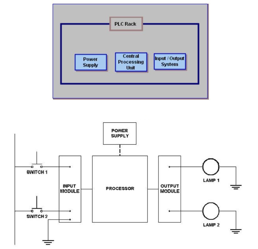
The PLC is a microprocessed device, constituted by a system microprocessor or a microcontroller, a monitor program, a program memory, a data memory, one or more input interfaces, one or more output interfaces and auxiliary circuits.

Power supply
The power supply of a PLC is intended to convert the supply voltage (110 to 220 VAC) to the supply voltage of the electronic circuits (5 Vcc for the microprocessor, memories and auxiliary circuits e12 VCC for communication with the programmer or computer ), as well as maintain charge the battery and provide voltage for the input and output power (12 or 24 VDC).
Processing unit
The CPU is responsible for the logical operation of all the circuits. In modular PLCs, the CPU is usually contained in a single card separated from the others. Already in PLC of smaller size, the CPU and the other circuits are generally contained in the same plate.
Battery
The battery used in PLC is intended to maintain the power of the real-time clock circuit and maintain the parameters or (when RAM memory is used), even in the absence of electrical power.
Monitor program memory
The monitor program is responsible for the general operation PLC, administering all PLC activities. This program can not be changed by the user, being stored in memories of the PROM, EPROM or EEPROM type, and works in a similar way to the operating system of the computers.
User memory
In this memory, the program developed by the user, which can be changed, making the programming flexible. This program is usually stored in RAM, EPROM, EEPROM and FLASH-EPROM memories, whose capacity varies according to the PLC model.
Data memory
Its purpose is to store the program data of the user, such as values of timers, counters, passwords, etc. In general, the data memory uses parts of the RAM memory of the PLC.
Input and output memory
This memory stores information about the states of the inputs and outputs of the PLC, functioning as a table where the CPU will look for information during the processing of the user program.
Auxiliary circuits
They are circuits responsible for the protection of faults in PLC operation, such as:
• Avoid the improper activation of the outputs when PLC power;
• Avoid the loss of information in the event of PLC deenergization;
• Avoid processing errors, identifying faults in the system microprocessor that emits error information.
PLC inputs and outputs
All PLCs have the same basic components. These components work together to bring information to the PLC from the field, evaluate that information and send information back to various fields. Without any of these major components, the PLC will not function properly.
Digital (discrete) and analog variables are present in a process. Analog variable is understood to mean that it varies continuously as a function of time, such as, for example, the temperature of a room, which can assume any value within a certain range. Digital variables, on the other hand, assume binary situations, such as, for example, motor on or off, presence of a person or not.
For a PLC, through a program, to adequately control a certain process, it is necessary that it has input/output devices compatible with the process variables and with the desired control strategies.
The input and output (I/O) modules of a PLC connect the interface with the external system. There are several types of modules (analog, digital and intelligent), with a variable number of inputs and outputs. The PLC input modules receive signals from sensors and field buttons. The output modules communicate to the actuators what the control or signaling action will be.
In medium and large-sized PLCs, the I/O modules are fitted in slots located in the CPU box (Central Processing Unit) or in a separate expansion rack, allowing flexibility in the configuration of the PLC. The use of slots also allows the damaged module to be replaced quickly.
In small PLCs (microPLCs), the number of inputs and outputs is small and fixed (less than eight) and generally consists of digital signals.
The digital I/O modules operate with signals from two states: ON or OFF. The digital input modules are capable of detecting and convert input signals to logic voltage levels used in the PLC; the digital output ones convert the logic output signals used in the PLC into proper signals capable of energizing the actuators.
Some digital I/O modules work with continuous signals; others operate with alternating signals. For use in DC (direct current), the standard voltage value adopted is 24 V, as it allows a signal/noise ratio suitable for industrial environments. For AC modules (alternating current), the standard is 110 or 220 V.
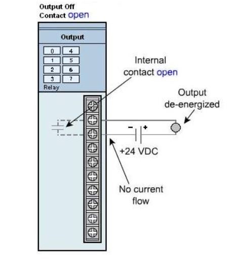
Discrete Module (Relay)
The term refers to an Off switching output. One type of PLC module that produces discrete signals is a relay module. It has a physical relay that opens or closes to make or interrupt a circuit connected to its terminals. The relay modules have several pairs; each of which is connected to the relay's internal contacts.
Open contact
Closed contact

Discrete Module (Transistor)
Another type of discrete module is the sinking output module, so named because conventional current flows to its terminal when a specific output is turned on. Conventional current flows from a positive to a negative potential.

Output not activated

Output activated

Representation of events when the output is activated:
1 - An NPN transistor is activated
2 - The output terminal goes to LOW
3 - Conventional current flows from the positive of the power supply through the field device to the sinking terminal of the output module through the transistor to the negative of the power supply.
AC input modules
AC input modules detect the presence or absence of AC voltage and convert that voltage to a low level for input to the CPU. The AC voltage indicates the status of the field device. The voltage level is usually 24, 110 or 220 VAC. The modules are available for up to 1,000 VAC. A schematic diagram of the AC input module is shown below. When the field device completes the input circuit, there is a path to AC. An LED on the front of the module indicates that the input is present.

A rectifier converts AC to DC. The optical coupler isolates the CPU input module and effectively reduces the DC voltage level to a safe level for CPU operations.
Most AC input modules use an external AC power supply for "interrogating" field devices. Integrated AC power supplies increase the size of the module and require additional heat dissipation considerations.
AC inputs can use a common neutral connection for multiple points or there can be an "isolated" neutral for each point for additional protection against failures. The input module shown in the image above uses C1 neutral for points 00-07 and C2 neutral for points 10-17. Analog AC input modules are not commonly used because there are no standardized analog AC current or voltage signals.
DC digital input modules
Discrete DC input modules detect the presence or absence of DC voltage and convert this voltage to a low level for input to the CPU. The DC voltage is used to indicate the status of the field device. The image below shows a schematic diagram of the DC input module.

The DC voltage can be supplied by the input module (collector input) or it can be supplied by an external power supply (source input).
As with AC input modules, the input is coupled to the CPU for CPU isolation and protection. An LED provides an indication when the input is present (true).
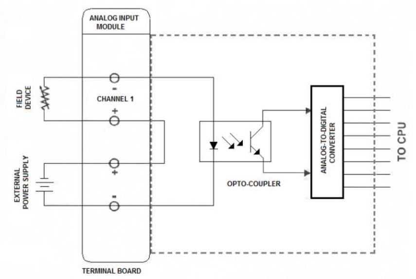
DC analog input module
The analog DC input modules detect a DC voltage or current level, convert this variable into a proportional digital signal and transmit this data to the CPU for processing. The modules can be configured to operate in standard instrumentation signal ranges, such as 4-20 mA, 10-50 mA, 0-10V.
A schematic diagram of an analog DC input module is shown below:
After the module converts the analog value to digital, the PLC can activate and deactivate the control functions in predefined analog values. For example, when the analog input value reaches 70%, an alarm sounds.
AC output modules
The AC output modules control the ON / OFF states of the AC output field devices, such as relays, coils and solenoids. They typically do not use power for field devices. The image below is a schematic diagram of the module.

The CPU uses a low voltage DC signal to activate an optocoupler on the output module. The opto-coupler activates a TRIAC or SCR which, in turn, completes the current path to the external power supply and the field device. As with most PLC modules, the voltage rating and number of points are selectable and the outputs can have common or isolated neutrals.
DC discrete output modules
Discrete DC output modules control the on/off states of the DC output field devices. The power is supplied by an external power supply. A schematic diagram of the module is shown below:

The CPU sends a low-level DC signal to an optocoupler that completes the path of the external DC current that energizes the output field device. Field device connections can be "sinked" or "sourced".
DC analog output modules
Analog DC output modules convert digital data from the CPU into analog data for use in the field device. A digital to analog converter (D/A) on the module performs the conversion. Below for a schematic diagram of the module.

Analog outputs conform to standard instrumentation signals (4-20 mA, 10-50 mA, 0-5V, 0-10V). An external DC power supply is used to power the output field device and the optical coupler on the module.
Digital Inputs and Outputs
In a process, digital variables are present (discrete) and analog variables. Analog variable is understood as one that varies continuously as a function of time, such as, for example, the temperature of a room, which can assume any value within a given track. Already the digital variables assume binary situations such as, for example, the connected motor or and in the case of a person or not.
For a PLC, through a program, to adequately control a certain process, it is necessary that the process even has input/output devices compatible with the process variables and with the desired control strategies.
The input and output (I/O) modules of a CLP connect the interface with the external system. There are several types of modules (analog, digital and intelligent), with variable number of inputs and outputs. The input modules of the CLP receive signals from the sensors and from the field buttons. The output modules communicate to the actuators what the control or signaling action will be.
In medium and large size PLCs, the I/O modules are embedded in slots located in the CPU box (central processing unit) or in a separate expansion rack, flexibility in the configuration of the CLP. The use of the slots also allows the damaged module to be replaced quickly.
In small PLCs (micro-PLC), the number of inputs and outputs is small and fixed (less than eight) and is generally reduced to digital signals.
The digital I/O modules operate with two-state signals: on or off. The digital input modules are capable of detecting and converting input signals into logical voltage levels used in the CLP; the digital output converts the logic output signals used in the CLP into own signals capable of energizing the actuators.
Some digital I/O modules work with continuous signals; others operate with alternate signals. For use in DC (direct current), the standard voltage value adopted is 24 V, since it allows an adequate signal-to-noise ratio for industrial environments. Already for the AC (alternating current) modules, the default value is 110 or 220 V.
Digital Inputs
Despite physical variables, such as temperature, pressure, force, mass, etc., have analog behavior, most of the processes are controlled through digital information, coming from sensors, boot, end-of-stroke keys, thermostats, pressure switches, etc., making the digital inputs more present and the most used in PLC.
Devices:
• Microswitches.
• Push-button switches.
• End of course switches.
• Automatic switches.
• Logical ports.
• Photovoltaic cells.
• Contacts of motor starters.
• Relay contacts.
• Pressure switches
• Thermostats.
• Proximity sensor.
• Presence sensor.
Digital Outputs
The digital outputs are the most used in PLCs due to their simplicity, since they can assume only two situations, triggered and disconnected. When a digital output is activated, it behaves like a closed switch, energizing the actuator device. When a digital output is turned off, it behaves like an open switch, de-energizing the actuator device.
Devices:
• Alarms.
• Control relays.
• Lamps.
• Logical ports.
• Horns.
• Motor starters.
• Electric valves.
• Solenoids.
• Contactor coils that drive loads of high currents and voltages.
• Pneumatic valve solenoids.
• Solenoid valves.
• Switches.
• Small engines.
Analog Inputs and Outputs
Analog Inputs
The analog inputs of a PLC are generally used in processes that require more precise control, identifying and updating each scan the instantaneous value of the input variable. The main physical variables measured by analog inputs are temperature and pressure. For this, devices such as pressure sensors and thermocouples are used, which convert the physical variables into proportional electrical signals, whose amplitudes are recognized by the inputs analog of the PLC. These electrical signals can be voltage or current, the range of values used is, respectively, 0 to 10 Vdc and 4 to 20 mA.
Devices:
• Various transducers;
• Electronic transmitters;
• Analytical instruments;
• Potentiometers.
Analog Outputs
The analog outputs of a CLP are generally used in processes that require more precise control, adjusting the operation of the actuators to the needs of the process. The electrical signals of the analog outputs can be voltage or current, whose range of values used is, respectively, 0 to 10 Vdc and 4 to 20 mA. In this way, the actuators will receive variable electrical signals from the analog outputs, not only energizing the equipment, but, mainly, defining the intensity of their performance in the process.
Devices:
• Analog indicators;
• Motor drives;
• Registers;
• I/P Transducers;
• Electric valves.
Addressing
To work with analog signals, PLCs need an analog-digital converter (A/D) in the inputs and, similarly, of a digital-analog converter (D/A) in the outputs.
The following table shows the characteristics of the analog inputs for a generic CLP.

The following table shows the addressing of the analog inputs.

The following table shows the characteristics of the analog outputs for a generic CLP.

The following table shows the addressing of the analog outputs.

Unregistered user. Buy the training at jats.com.br.