First Project
• Open Rockwell Studio 5000.
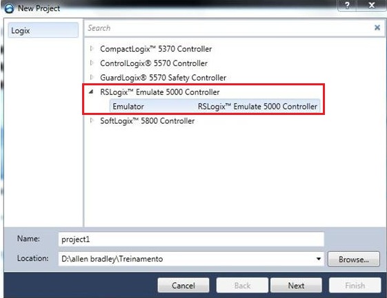
• Create a new project. Select item Create > New Project.

• Select the RSLogix Emulate 5000 driver. Define project name as project1. In Location, select the project storage location.
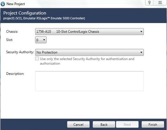
• Select chassis 10-Slot 1756-A10 and Security authority as No Protection.
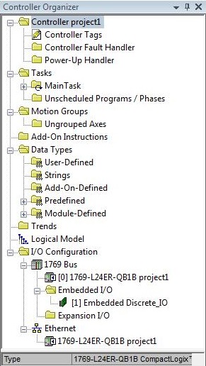
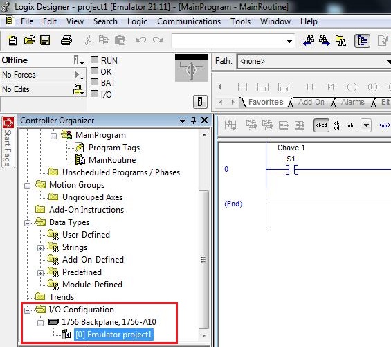
Structure of the project created:
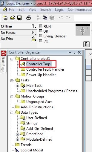
• In Controller Organizer, open Controller project1 > Controller Tags (double click of the mouse).
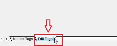
• Select the Edit Tags tab.
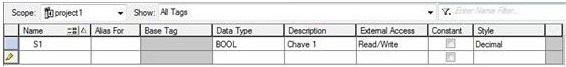
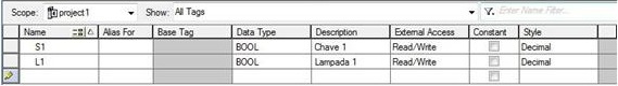
• Insert tag S1 of type BOOL and Switch 1 as description.
• Insert tag L1 of type BOOL and Lamp 1 as description.
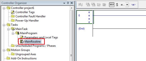
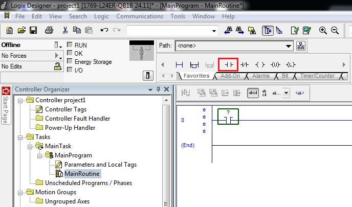
• Open the main routine for editing. In Controller Organizer, double click on Tasks > MainTask > MainProgram > MainRoutine.
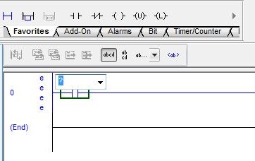
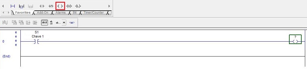
• Insert a normal open contact in rung 0. Select the rung 0 and then click on the normal contact opened in Favorites.
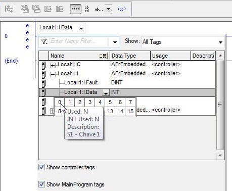
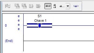
• Enter with the label S1 - Key 1 as operating of the Examine On instruction (normally open contact). Give two clicks on the operand of the company Examine On instruction. Select the tag option S1.Insert a normally open contact in rung 0. Select rung 0 and then click on the normally open contact in Favorites.
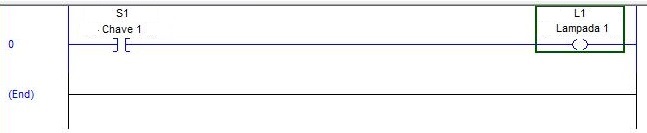
• On the right side of rung 0, insert a Output Energized instruction (coil).
• Enter with the tag L1 - Lamp 1 as operand of the Output Energize instruction.
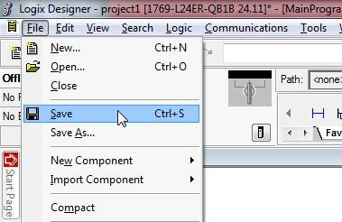
• Save the project on File > Save. menu item
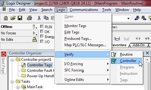
• Check the existence of errors in the project. Select Logic > Verify > Controller menu item.
Simulation with RSLogix Emulate 5000
During simulation, the created program is not processed in PLC, but on the computer on which RSLogix is running. This allows you to test the logic of the program without the PLC hardware.
RSLogix Emulate 5000
RSLogix Emulate 5000 is a software that emulates the process ControlLogix controller behavior. The emulator allows you to experience and debut the RSLogix program in security, without investing in physical controllers and I / O modules. RSLogix Emulate 5000 also allows you to test HMI applications, without using a real controller.
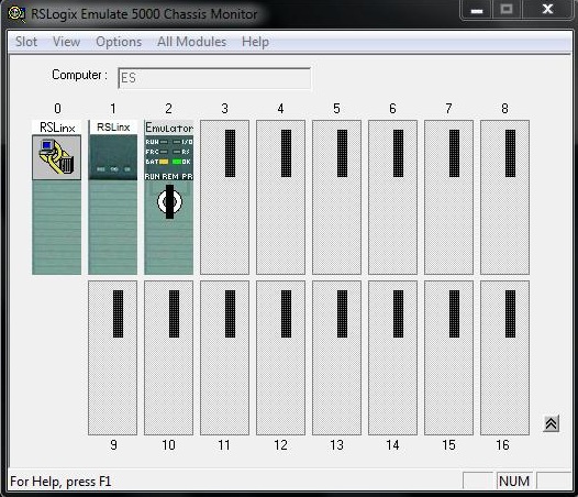
The Chassis Monitor tool allows you to create, delete, monitor and configure modules in a virtual chassis. It is also possible to change the virtual controller mode and see its status in the simulated LEDs.
• Open RSLogix Emulate 5000.

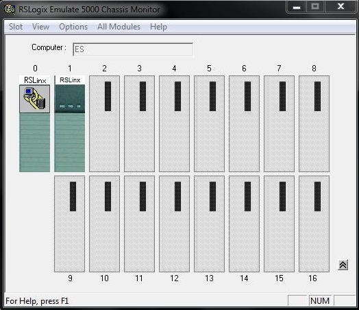
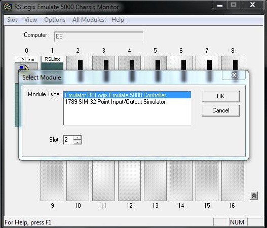
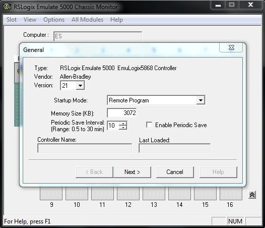
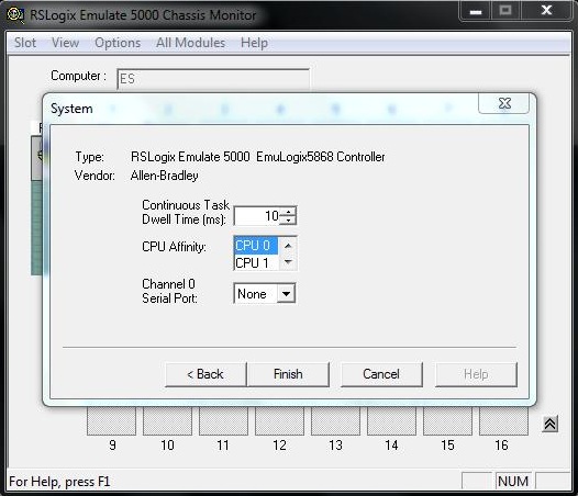
• Insert virtual controller into slot 2 of the chassis. Click with the right mouse button on slot 2 and select the menu item Create... Next, select the module type Emulator RSLogix Emulate 5000 Controller.
RSLinx
RSLinx is the software that connects Allen Bradley devices and networks with Microsoft Windows applications.

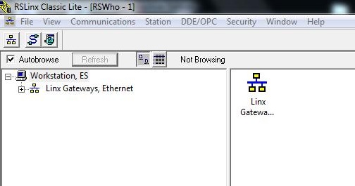
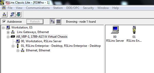
RSWho is the main RSLinx Classic window that shows devices and networks in a style similar to Windows Explorer.
Before the emulator can communicate with RSLogix 5000, it is necessary to create a communication controller for the emulator using RSLinx.
• Open RSLinx Classic.
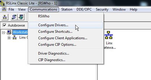
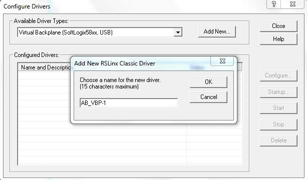
• Select Communications > Configure the controller... menu item.
• Select the virtual display driver (SoftLogix58xx, USB) in the Avaliable Driver Types list.
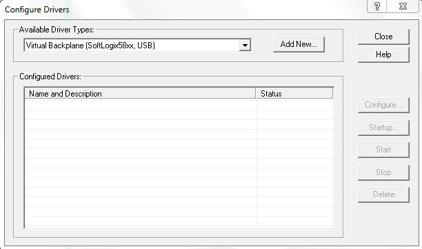
• Select the name of the driver. Keep the pattern shown AB_VBP-1.
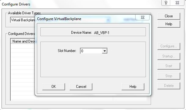
• In the Slot Number field, the slot number where the emulator will reside is specified. Keep the default value 0.
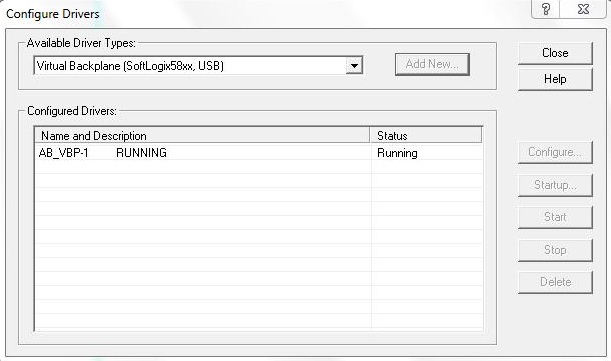
Note the driver AB_VBP-1 running (Status = Running).
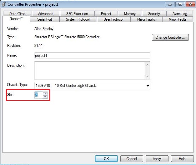
• In the RSLogix 5000, setting the slot corresponds to the slot which contains the emulator in the RSLogix Emulate 5000 Chassis Monitor (slot 2).
• Select menu item Edit Controller > Properties, Open the General tab and in the Slot field enter the value 2.
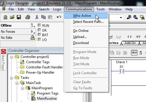
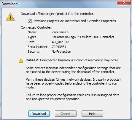
• Download the program in RSLogix 5000 for the emulator in RSLogix Emular 5000. Select Communications > Who Active.
• Select channel 02, RSLogix 5000 Emulator, Emulator R21.11 and then click the Download button.
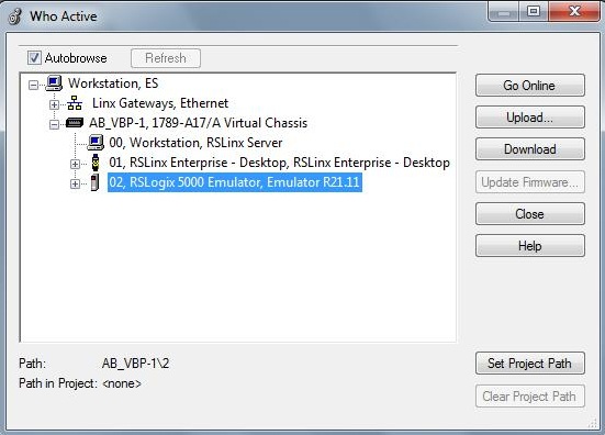
• Confirm Download.
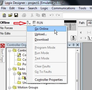
• Place the project in RSLogix in Online mode to monitoring and control. Click on the icon indicated in the image below and select Online menu item.
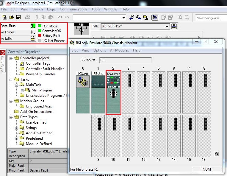
• Observe the RUN LED on the emulator (RSLogix Emulate 5000) in green and the LED Run Mode in the project (RSLogix 5000) also in green.
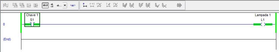
• In MainRoutine, observe the key S1 with logic level "0" and L1 lamp with a logic level "0".
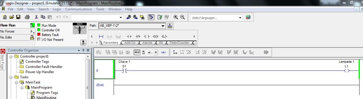
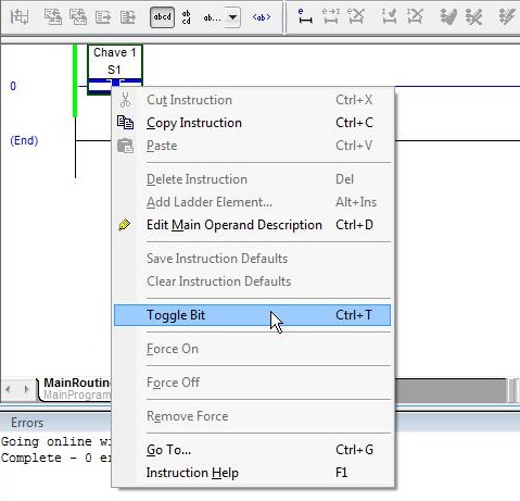
• Change the logical level of the S1 switch to "1". Right-click on the normal open contact of S1 and select the Toggle Bit menu item. The Toggle Bit function reverses the current value ("0" to "1" or "1" for "0").
• Observe S1 switch with logic level "1" and L1 lamp with logic level "1" (operated).
Next
Unregistered user. Buy the training at jats.com.br.